Supercharge Your Innovation With Domain-Expert AI Agents!

Linkage interlocked padlock head

A blade lock and blade technology, which is applied in the field of locks, can solve the problems of different opening actions, enlarged axial and radial dimensions of the lock body, etc., and achieve the effect of good anti-prying and simple structure.

Inactive Publication Date: 2006-12-13
安雨青
View PDF1 Cites 2 Cited by
  • Summary
  • Abstract
  • Description
  • Claims
  • Application Information

AI Technical Summary

Problems solved by technology

However, in some applications, such as ferrule heads, no matter whether the rotor adopts an integral structure or a split structure to achieve the above actions, due to the space required for the connection and installation of the auxiliary blade and the locking lever and the installation of the return spring of the auxiliary blade, Both will increase the axial and radial dimensions of the lock body. In addition, due to the axial force generated by the auxiliary blade return spring, the opening action will be different from that of ordinary blade locks.

Method used


Image

  • Linkage interlocked padlock head
  • Linkage interlocked padlock head
  • Linkage interlocked padlock head

Examples


Embodiment Construction

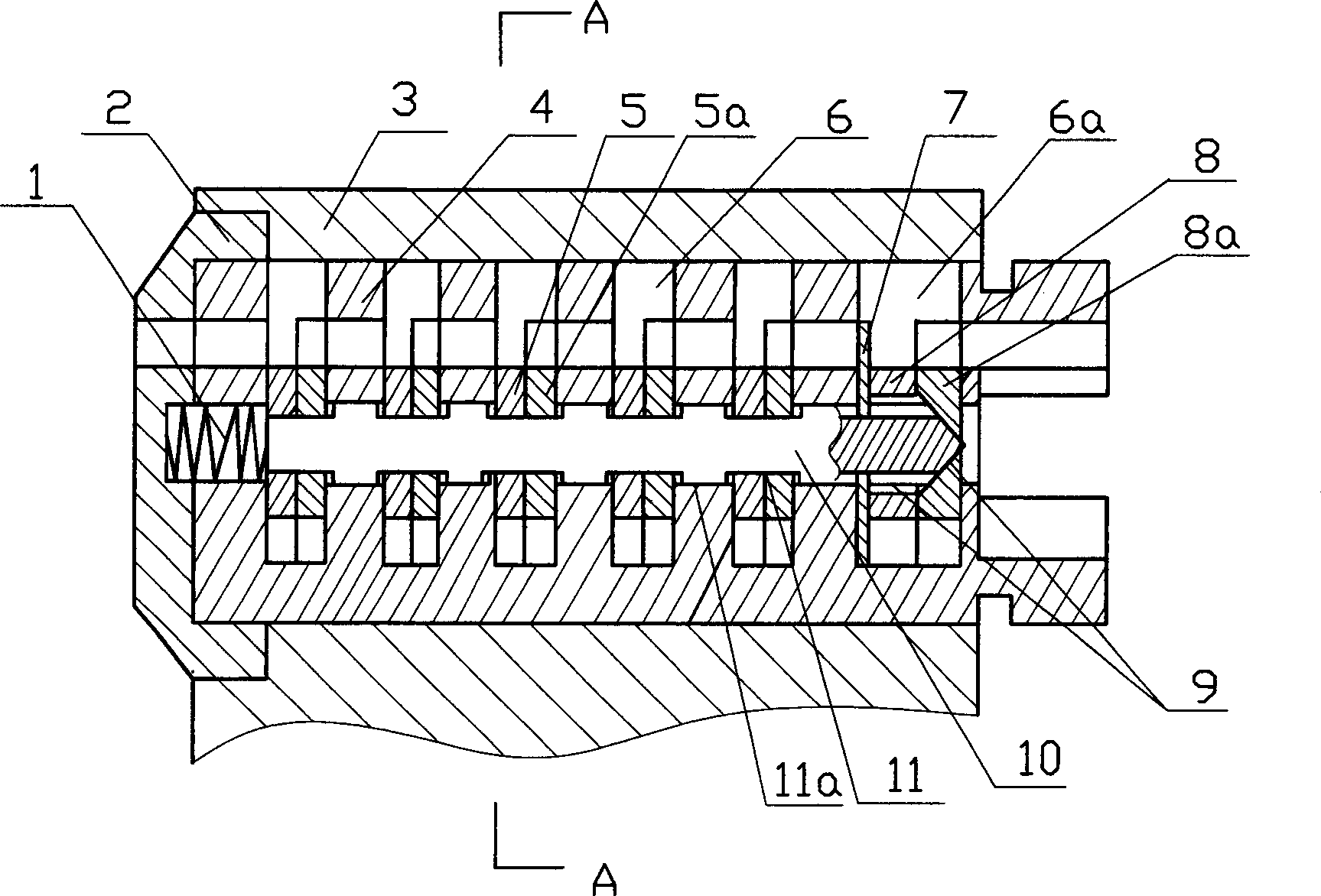
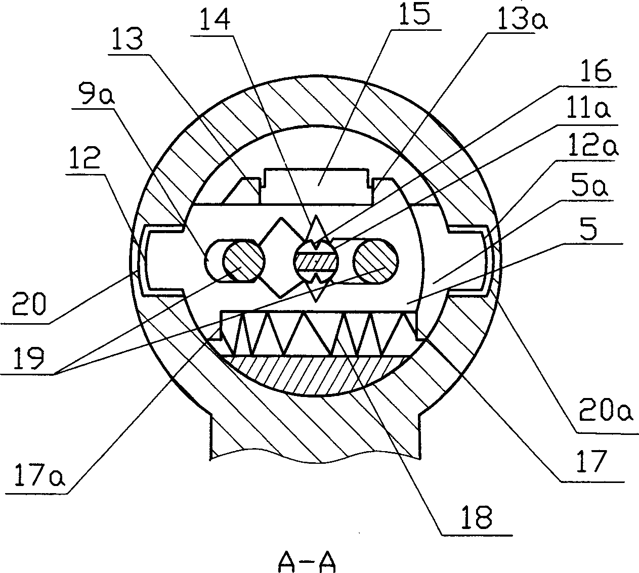
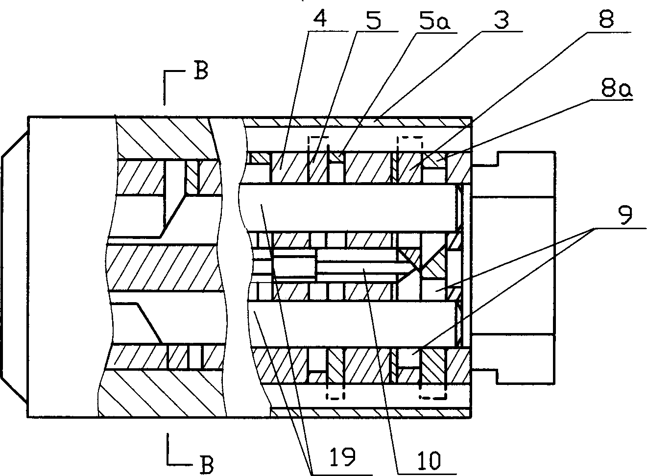
[0016] As shown in the figure, the lock body 3 has a round hole in the axial direction, and the entire rotating core 4 assembly is installed in the round hole. The left end of the lock body 3 is equipped with an anti-tamper cover 2, and the inner wall of the round hole is symmetrically provided with two locking grooves 20, 20a, the rotating core 4 is radially provided with five parallel blade transverse grooves 6 and one auxiliary blade transverse groove 6a, and five pairs of blades 5, 5a and a pair of auxiliary blades 8, 8a are respectively arranged in the blade transverse grooves 6 and the auxiliary blade transverse grooves In 6a, each pair of blades 5, 5a and auxiliary blades 8, 8a elastically cooperate with the return spring 18 through the ribs 17, 17a provided at the bottom, and under the action of the return spring 18, the blades 5, 5a, auxiliary blades 8, The blade lugs 12, 12a of 8a are inserted into the locking grooves 20, 20a. The rotating core 4 is axially provided ...


PUM


Abstract

The invention relates to a linkage blade lock head. Wherein, the rotating pin has one group of blade grooves radial; the key hole is arranged axially; the blades is arranged inside the blade grooves; the rotating pin is mounted inside the pin head; the protruded era of blade is inserted matched with the lock groove of lock head; the auxiliary blade groove at the right of rotating pin is arranged with one or two auxiliary blades that flexibly matched; its protruded ear is inserted matched with lock groove; the lock rod matched with blade lock is axially arranged inside the lock pin; the right end of lock rod is contacted matched with the incline surface of auxiliary blade, while the left end is matched with return spring. Since the invention uses auxiliary blade, lock rod, and blades which are linked, the auxiliary blade will clamp the lock head or move the lock rod to lock the blade, the invention can obtain better anti-theft ability with simple structure, while it can avoid increase size, but directly use present lock head.

Description

technical field [0001] The invention belongs to the technical field of locks, and in particular relates to a lock head of a linkage interlocking blade lock. Background technique [0002] The blade lock is evolved from the tumbler lock, and is currently widely used because it has better anti-prying and anti-theft functions than ordinary tumbler locks. However, because the general blade lock only replaces the original pins with blades and simply improves the corresponding structure, it cannot completely overcome the inherent defects of mechanical locks, and still has potential safety hazards of being pried and stolen. In view of this, the applicant had previously applied for and obtained a utility model patent named "Lock Head of Pull Bar Locking Anti-theft Lock", and the patent number is 200420023023.6. In this patented technical solution, the linkage and interlocking of the vane and the auxiliary vane is realized in this way: first, the vane moves to the open position under...

Claims


Application Information

Patent Timeline
IPC IPC(8): E05B29/02E05B17/20
Inventor 安雨青
Owner 安雨青
Features
  • R&D
  • Intellectual Property
  • Life Sciences
  • Materials
  • Tech Scout
  • Unparalleled Data Quality
  • Higher Quality Content
  • 60% Fewer Hallucinations
Learn More