
Muffler for hermetic rotary compressor

A rotary compressor and muffler technology, applied in the field of compressor devices, can solve the problems of increasing compressor noise, high-pressure gas leakage, reducing the efficiency of the muffler 11, etc.

Inactive Publication Date: 2006-12-20
LG ELECTRONICS (TIANJIN) APPLIANCES CO LTD
View PDF0 Cites 3 Cited by
  • Summary
  • Abstract
  • Description
  • Claims
  • Application Information

AI Technical Summary

Problems solved by technology

[0008] However, the flat-top muffler 11 shaft hole 15 of the usual above-mentioned structure is relatively large, and the shaft hole 15 forms a gap with the neck shaft of the upper bearing 7, which causes the leakage of high-pressure gas, greatly reduces the efficiency of the muffler 11, and increases Loud compressor noise

Method used


Image

  • Muffler for hermetic rotary compressor
  • Muffler for hermetic rotary compressor
  • Muffler for hermetic rotary compressor

Examples


Embodiment Construction

[0037] The present invention will be described in detail below in conjunction with the accompanying drawings and embodiments.

[0038] The same symbols are used for the same parts in the figures.

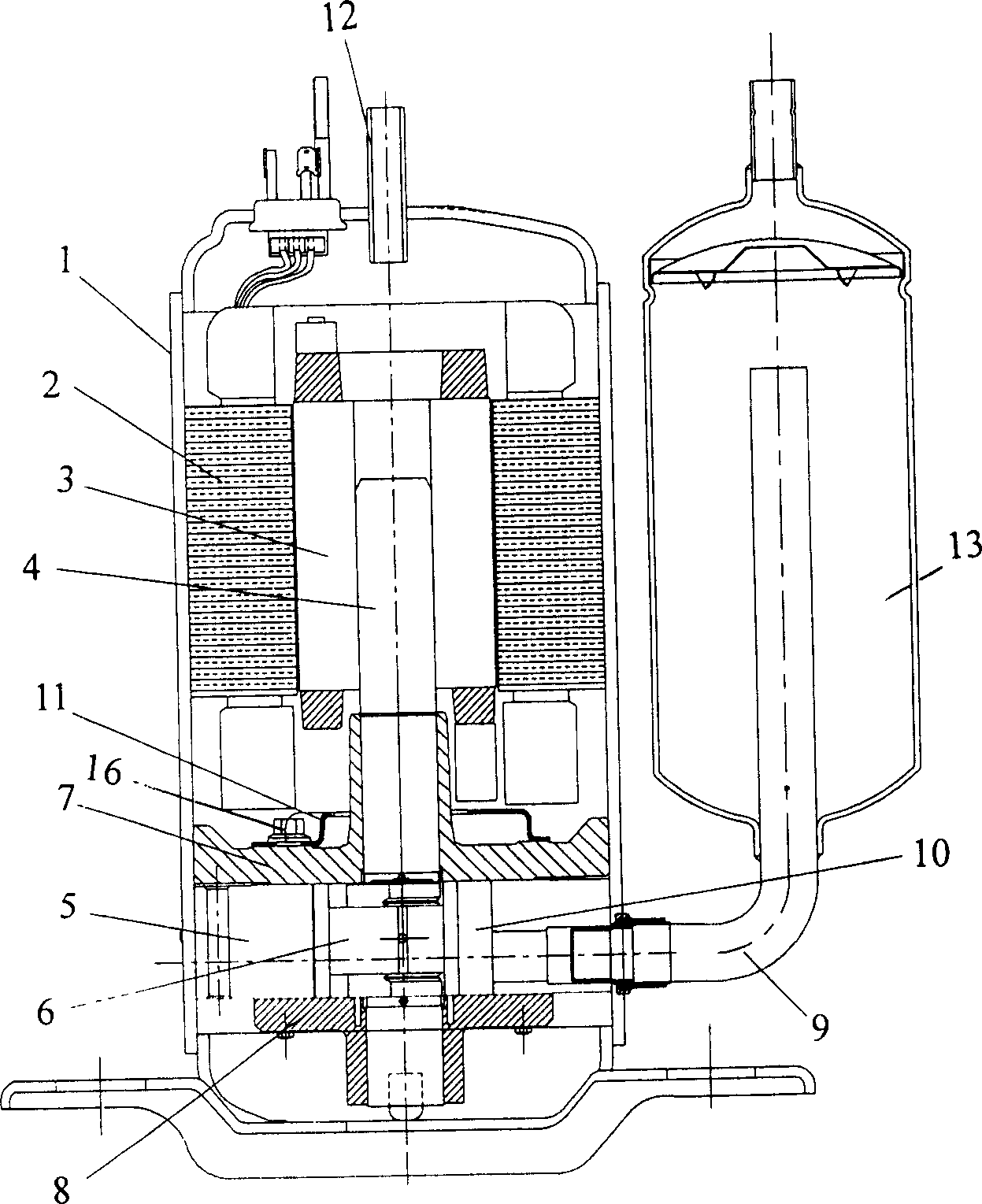
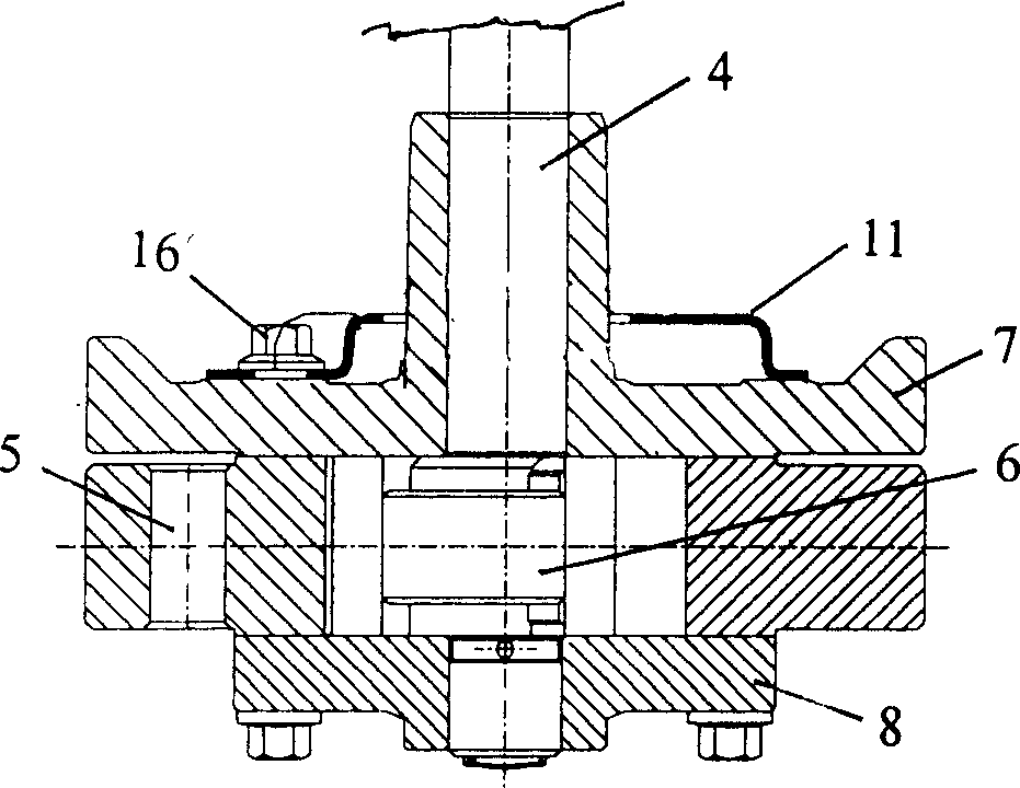
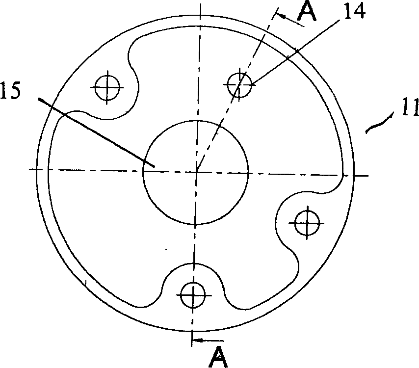
[0039] A muffler for an airtight rotary compressor, comprising a motor stator 2 and a rotor 3 arranged in the upper part of an airtight casing 1, a compressor is arranged at the lower end of an eccentric shaft 4 in the center of the rotor 3, and a compressor cylinder body at the lower part of the airtight casing 1 5, there is a rolling piston 13 on the outer peripheral surface of the eccentric part 6 of the eccentric shaft 4, and the upper and lower end surfaces of the cylinder block 5 are fixed with an upper bearing 7 and a lower bearing 8 that are sealed and support the rotation of the eccentric shaft 4, and the upper bearing 7 is installed with The muffler 11 that penetrates the neck shaft of the upper bearing 7 through the shaft hole 15 ; the outer ring wall 17 that is sealed wi...


PUM


Abstract

The invention relates to a sound absorber of sealed rotation compressor, which comprises a motor stator and a rotor mounted at the upper part inside the compressor frame; the lower end of eccentric axle at the middle of rotor is arranged with compressor; inside the cylinder at the lower part of sealed frame, the eccentric part of eccentric axle is arranged with rolling piston; the upper and lower ends surfaces of cylinder are fixed with upper and lower bearings that supporting the rotation of eccentric axle; the upper bearing is mounted with a sound absorber through the axle hole into the upper bearing neck axle; the axle hole and the neck axle are sealed connected. The invention can avoid the leakage of high pressure gas, via the seal connection between the axle hole and the neck axle, to improve the efficiency and reduce the noise.

Description

technical field [0001] The invention relates to a device for a compressor, in particular to a muffler for a hermetic rotary compressor. Background technique [0002] In general, compressors are classified into hermetic compressors or separate compressors according to the configuration of the motor and compressor. Among them, the hermetic compressor is that the motor and the compressor are arranged together in a hermetic container. figure 1 It is a schematic diagram of a longitudinal section structure of a hermetic rotary compressor in the prior art; figure 2 yes figure 1 Partial enlarged view of image 3 It is a top view structure schematic diagram of the muffler of the hermetic rotary compressor in the prior art; [0003] As shown in the figure, in the hermetic rotary compressor in the prior art, the stator 2 and the rotor 3 of the motor are arranged in the upper part of the airtight casing 1, wherein the center of the rotor 3 has an eccentric shaft 4, and the lower en...

Claims


Application Information

Patent Timeline
IPC IPC(8): F04C29/06
Inventor 王苏豫
Owner LG ELECTRONICS (TIANJIN) APPLIANCES CO LTD
Learn More