
Lamp

A lamp holder and lighting circuit technology, which is applied in the field of lamps, can solve the problems that cannot satisfy the overheating of the large-scale lighting circuit of LED lamps, and achieve the effect of suppressing the overheating of the light source and improving the heat dissipation performance

Active Publication Date: 2006-12-20
TOSHIBA LIGHTING & TECH CORP
View PDF8 Cites 72 Cited by
  • Summary
  • Abstract
  • Description
  • Claims
  • Application Information

AI Technical Summary

Problems solved by technology

[0009] However, there is no disclosure about the lighting circuit in the above-mentioned Japanese Laid-Open Patent Gazette.
Therefore, in the LED lamp disclosed in the above-mentioned laid-open patent publication, it is impossible to meet the requirements of suppressing the size of the LED lamp and the overheating of the lighting circuit.

Method used


Image

  • Lamp
  • Lamp
  • Lamp

Examples


Embodiment Construction

[0096] Refer to the following Figure 1 to Figure 5 The first embodiment of the present invention will be described.

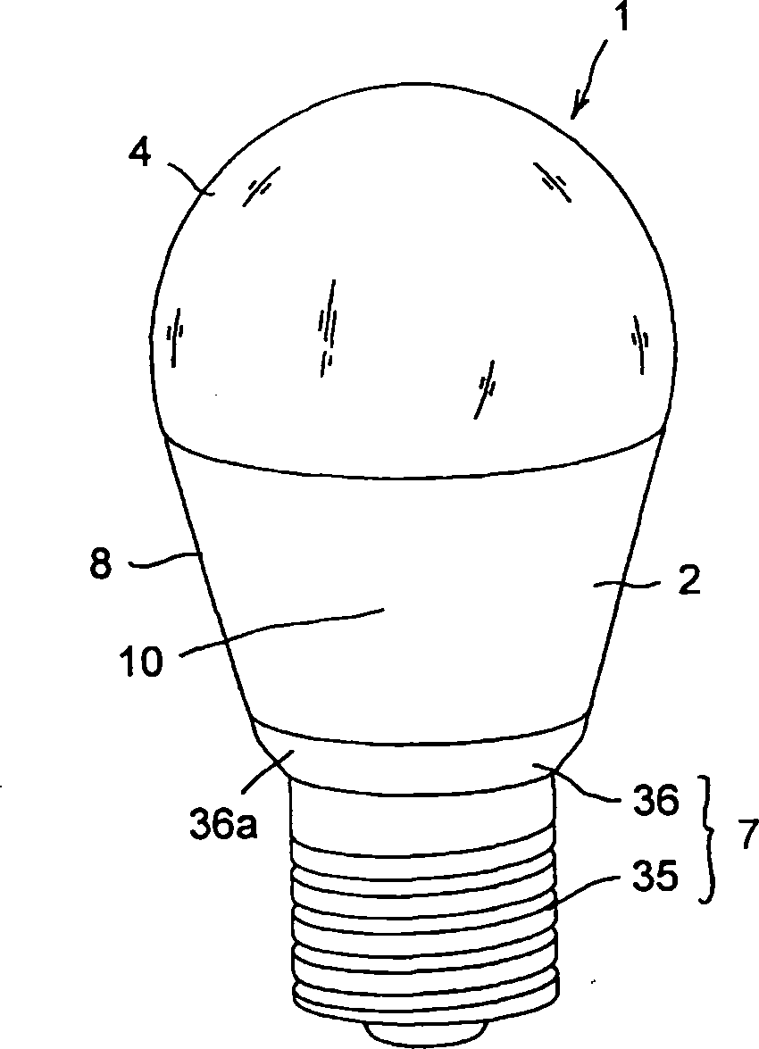
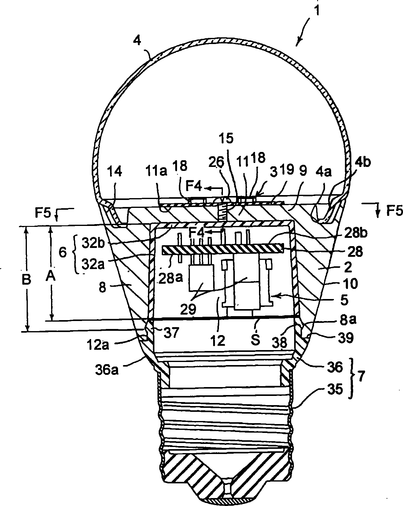
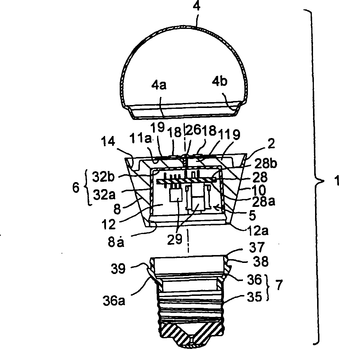
[0097] figure 1 as well as figure 2 A bulb-shaped lamp 1 compatible with incandescent lamps is disclosed. The lamp 1 includes an outer layer member 2 , a light source 3 , a transparent cover 4 , a lighting circuit 5 , an insulating member 6 , and a socket 7 .

[0098] The outer layer member 2 is made of a metal material having excellent thermal conductivity such as aluminum. Such as figure 2 as well as image 3 As shown, the outer layer member 2 includes a peripheral wall 8 and an end wall 9 . The peripheral wall 8 and the end wall 9 are integrally formed with each other. The peripheral wall 8 is formed in a cylindrical shape. The outer peripheral surface of the peripheral wall 8 serves as a heat dissipation surface 10 exposed to the outside of the lamp 1 . The heat dissipation surface 10 is formed in a tapered shape whose outer diameter gradually d...


PUM


Abstract

A lamp includes an outer shell having heat conductivity, a base provided in the outer shell, and a cover provided in the outer shell. The outer shell has a light source support, and a heat radiating surface exposed to the outside of the outer shell. The light source support is formed integral with the heat radiating surface. A light source is supported on the light source support. The light source is heated during lighting, and thermally connected to the light source support. The light source is covered with the cover.

Description

[0001] This application is based on the previous Japanese Patent Application No. 2005-112339 (applied on April 8, 2005), Japanese Patent Application No. 2005-221571 (applied on July 29, 2005), Japanese Patent Application No. 2005 - 221688 (filed on July 29, 2005), and Japanese Patent Application No. 2005-371406 (filed on November 26, 2005), and priority is claimed therein, the entire contents of which are disclosed herein as reference examples. technical field [0002] The present invention relates to a lamp using a semiconductor element such as a light-emitting diode as a light source, and particularly relates to a lamp capable of efficiently dissipating heat emitted from the light source to the outside of the lamp when the lamp is turned on. Background technique [0003] Light-emitting diodes are known as light sources for lamps that can replace incandescent lamps. As LEDs heat up, their light output will drop and their lifespan will shorten. Therefore, lamps using light-...

Claims


Application Information

Patent Timeline
Patent Type & Authority Applications(China)
IPC IPC(8): F21V29/00F21V17/00F21V23/00F21Y101/02
CPCF21K9/1355F21V3/00F21Y2101/02F21K9/23F21K9/238F21V19/0055F21V23/002F21V23/006F21V23/009F21Y2115/10
Inventor 大泽滋森川和人
Owner TOSHIBA LIGHTING & TECH CORP
Learn More