Rotor of motor and motor

A motor and rotor technology, applied in the field of motors, can solve the problems of stator induced voltage reduction and insufficient rotational driving force

Inactive Publication Date: 2006-12-20
HITACHI APPLIANCES INC
View PDF1 Cites 9 Cited by
  • Summary
  • Abstract
  • Description
  • Claims
  • Application Information

AI Technical Summary

Problems solved by technology

With such a structure of the rotor core, it is easy to generate leakage magnetic flux from the parts of the legs on both sides of the permanent magnet, so there is a problem that the induced voltage on the stator side is lowered, and when a large rotational driving force is required, it cannot be sufficiently obtained. The rotational driving force of

Method used


Image

  • Rotor of motor and motor
  • Rotor of motor and motor
  • Rotor of motor and motor

Examples


Embodiment Construction

[0029] Hereinafter, embodiments of the present invention will be described in detail with reference to the drawings.

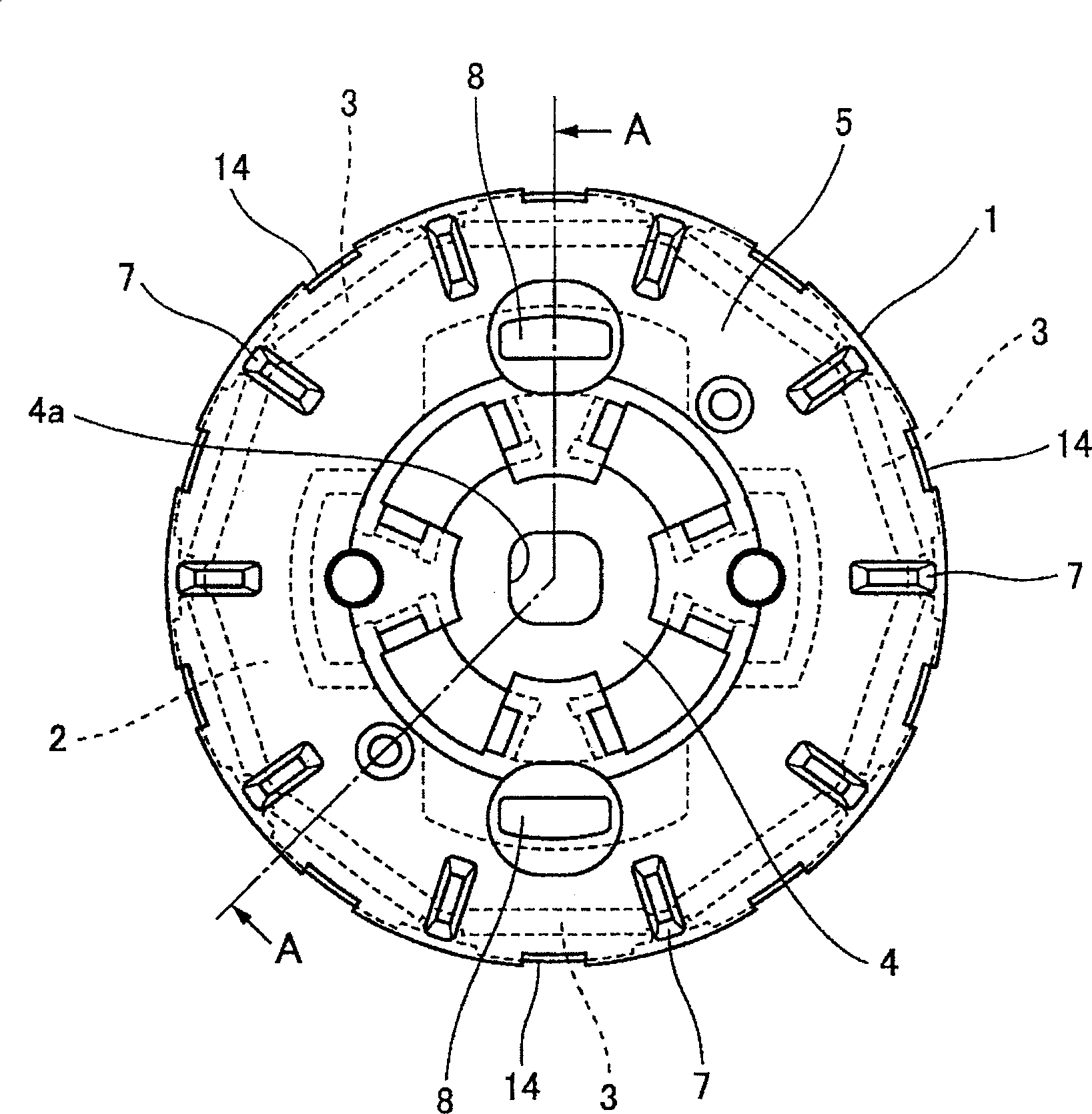
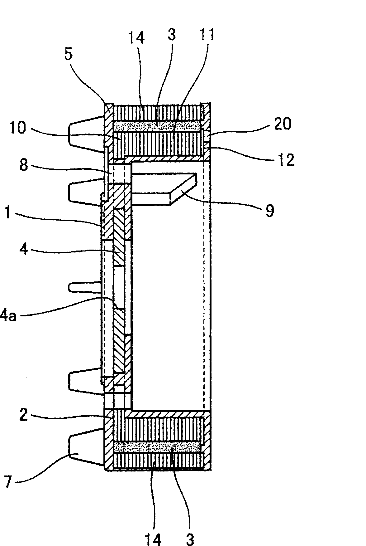
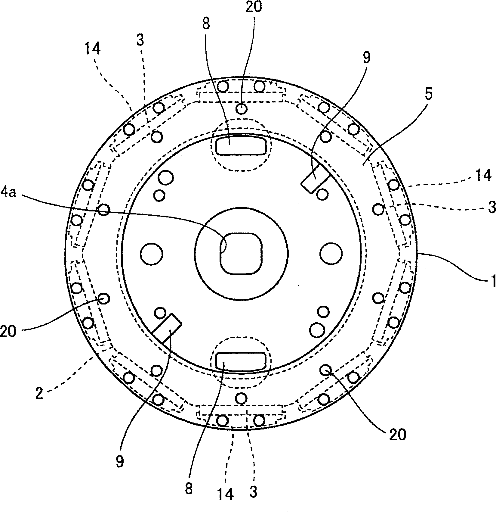
[0030] First, with Figure 17 The structure of the motor according to the present invention will be briefly described. Such a motor 30 has a rotor 1 connected to a rotating shaft 34 and a stator 32 fixedly provided to face the outer circumference of the rotor 1 . This type of motor is an inner type motor in which the stator 32 is arranged on the outside and the rotor 1 is arranged on the inside. Inside the rotor 1 of this motor, a rotor core 2 with a plurality of permanent magnets 3 loaded along its rotation direction is installed. On the other hand, an electromagnetic coil 32a is provided on the stator 32. The rotor 1 rotates relative to the stator 32 through the electromagnetic action between them, driving the rotating shaft 34 integrated with it to rotate.

[0031] The present invention relates to the structure of the rotor 1 used in such a motor 30 .

...


PUM


Abstract

The present invention provides a rotor core (2) having a structure in which electromagnetic steel plates are laminated, and a plurality of permanent magnets (3) made of rare earth materials arranged along the circumferential direction of the rotor core (2) In the rotor of the motor, the synthetic resin part (5) molded integrally with the above-mentioned rotor core (2) and the above-mentioned permanent magnet (3) is embedded, and the structure of the rotor core (2) is improved, thereby obtaining An electric motor with a large rotational driving force. The present invention is characterized in that, in the rotor core (2), the magnetic pole piece (14) disposed so as to protrude from the permanent magnet (3) to the stator side is configured so as to be completely separated from the main body of the rotor core (2). , Therefore, the leakage of magnetic flux can be suppressed and the induced voltage can be increased.

Description

technical field [0001] The present invention relates to a rotor of a motor used in washing machines and the like, and a motor having the rotor. Background technique [0002] Brushless motors are generally used as motors in washing machines and the like. This brushless motor consists of a stator with electromagnetic coils and a rotor with an iron core and permanent magnets inside. [0003] The structure of the rotor used in this motor has a rotor core, a plurality of permanent magnets made of clay material arranged along the circumferential direction of the core, and integrally molded in such a manner that the rotor core and the permanent magnets are embedded therein. Molded synthetic resin part. Here, the rotor core is formed by laminating a plurality of electromagnetic steel sheets, and the permanent magnets are arranged to be embedded in a plurality of holes formed along the circumferential direction of the rotor core (for example, refer to Patent Document 1 - Japanese U...

Claims


Application Information

Patent Timeline
Patent Type & Authority Applications(China)
IPC IPC(8): H02K1/27
Inventor 成田博文大川友弘丰田荣治小原木春雄榎本裕治石川俊一
Owner HITACHI APPLIANCES INC
Why Eureka
Try Eureka