Supercharge Your Innovation With Domain-Expert AI Agents!

Small-sized piezoelectric resonator

A piezoelectric resonator, vibrating arm technology, applied in the field of portable electronic equipment and small resonators

Active Publication Date: 2012-04-25
ETA SA MFG HORLOGERE SUISSE
View PDF7 Cites 0 Cited by
  • Summary
  • Abstract
  • Description
  • Claims
  • Application Information

AI Technical Summary

Problems solved by technology

However, although these three-arm resonators have proven to be advantageous, the need for miniaturization as well as the energy consumption required to maintain the vibration of the tuning fork have been important issues for applications such as mobile phones or watches.

Method used


Image

  • Small-sized piezoelectric resonator
  • Small-sized piezoelectric resonator
  • Small-sized piezoelectric resonator

Examples


Embodiment Construction

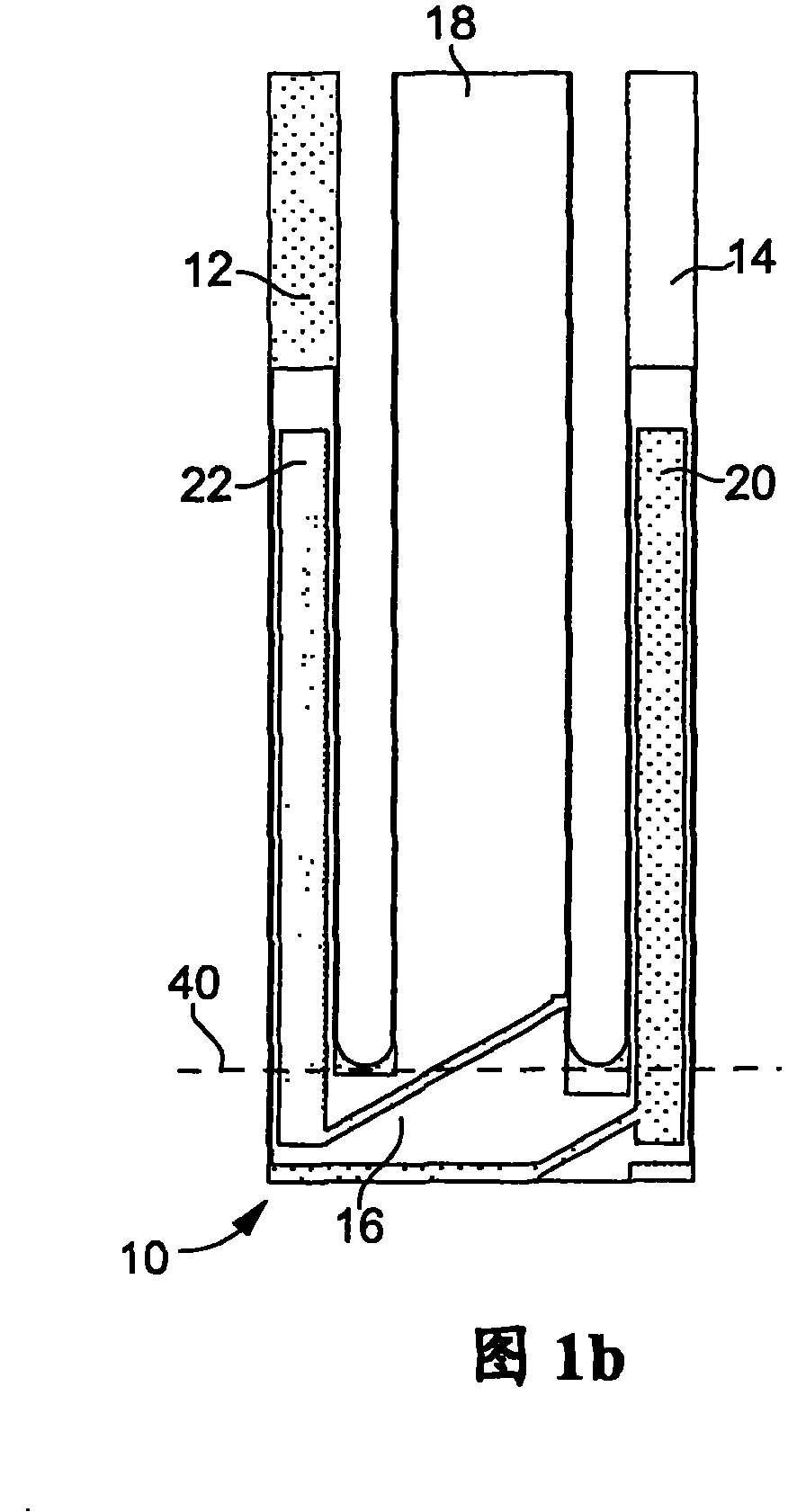
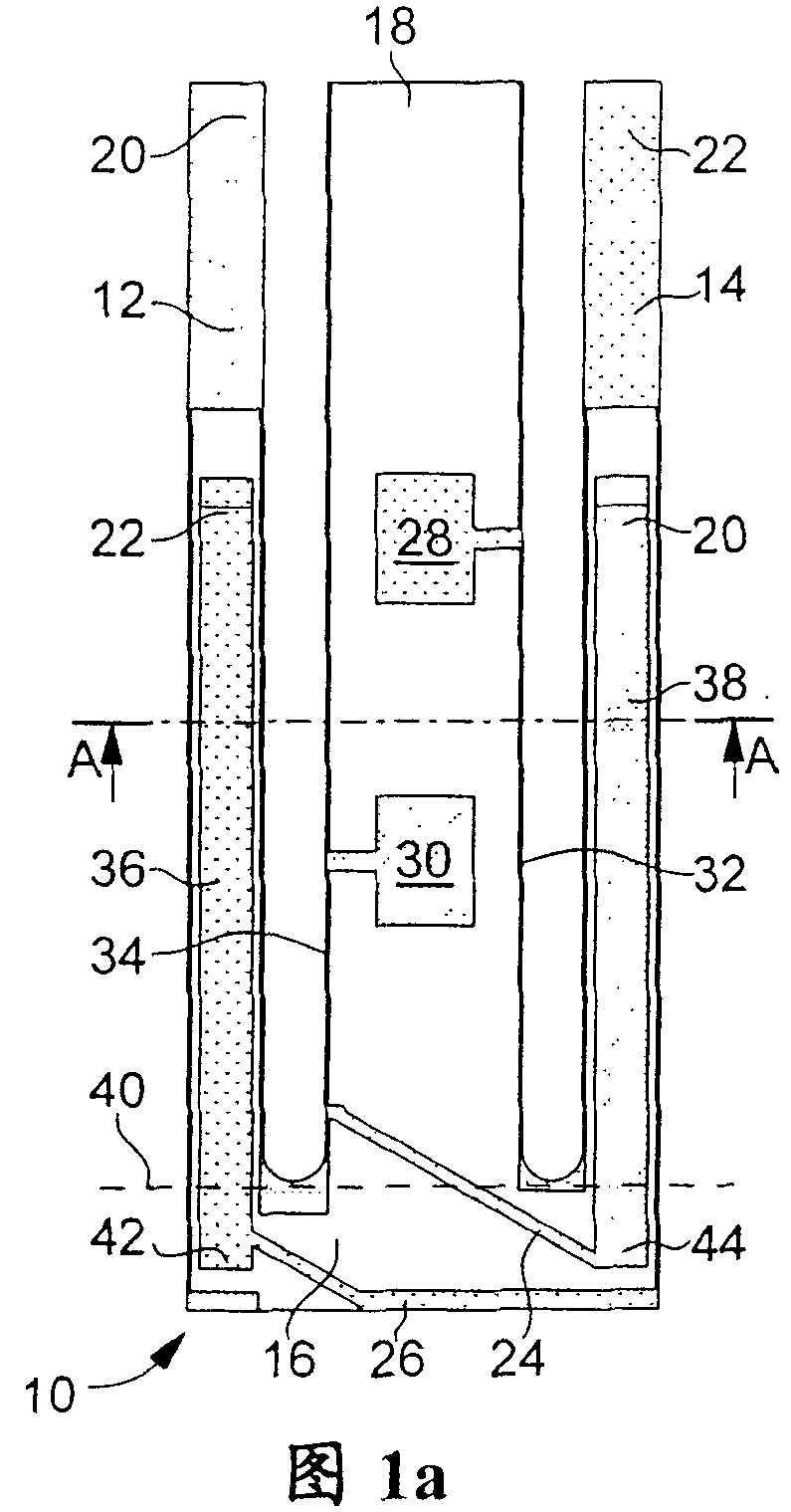
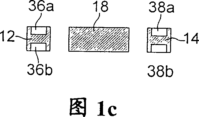
[0038] exist Figure 1a , In the first embodiment shown in 1b and 1c, the resonator according to the invention represented by the reference numeral 10 comprises a tuning fork-shaped part having two vibrating arms 12 and 14 connected by a connecting part 16, in which Attached to the connection part 16 is a central arm 18 positioned between and parallel to the arms 12 and 14, the whole assembly being made of quartz in one piece.

[0039] Such as Figure 1a with 1b As shown, the vibrating arms 12 and 14 carry two sets of electrodes 20 and 22 respectively connected to each other by conductive paths 24 and 26 carried by the connecting portion 16 of the tuning fork-shaped member. As shown in the figures, these electrodes and conductive paths are arranged so that the arms 12 and 14 vibrate in a flexural mode, but they could have different configurations to cause the arms to vibrate in the same mode or another mode (torsion, shear, etc.) vibration. For the center arm 18, Figure ...


PUM


Abstract

The piezoelectric resonator (10) according to the invention includes a tuning fork shaped part with two parallel vibrating arms (12, 14), connected to each other by a linking part (16), from which protrude a central arm (18) located between both vibrating arms of the tuning fork shaped part, wherein at least one groove (36, 38) is formed on at least one of a front side and a rear side of each vibrating arm.

Description

technical field [0001] The present invention relates to piezoelectric resonators, and in particular to small resonators most commonly used in the manufacture of frequency generators, especially for portable electronic devices in various fields such as clockwork, information technology, telecommunications and medical fields. Background technique [0002] Such a small resonator has been disclosed in prior art document US6700313 filed in the name of the assignee, which document is hereby incorporated by reference. Figure 13 The resonator 10 shown in for mounting in a housing comprises a tuning fork-shaped part having two parallel arms 12, 14 which are connected to each other by a connecting portion 16 and which carry electrodes 20, 22 to vibrate the electrodes , these electrodes are connected to connection tabs 28, 30 for electrical connection to the outside of the housing. The resonator 10 also includes a central arm 18 attached to the connection portion 16 and located betwee...

Claims


Application Information

Patent Timeline
Patent Type & Authority Patents(China)
IPC IPC(8): H03H9/15
CPCH03H9/215
Inventor S·达拉·皮亚扎B·施图德T·卢赛
Owner ETA SA MFG HORLOGERE SUISSE
Features
  • R&D
  • Intellectual Property
  • Life Sciences
  • Materials
  • Tech Scout
  • Unparalleled Data Quality
  • Higher Quality Content
  • 60% Fewer Hallucinations
Learn More