Device for handling components and method of controlling

A control method and a technology for manipulating components, which are applied in the direction of assembling printed circuits, electrical components, electrical components, etc. with electrical components, can solve problems such as blowing away and component movement, and achieve the effects of improving assembly efficiency, simple structure, and high reliability

Inactive Publication Date: 2006-12-20
SIEMENS ELECTRONICS ASSEMBLY SYST LLC
View PDF0 Cites 2 Cited by
  • Summary
  • Abstract
  • Description
  • Claims
  • Application Information

AI Technical Summary

Problems solved by technology

Here, especially when using very small components, the problem can arise that components already located on the substrate in the immediate vicinity can be displaced or even blown away by the impact of the compressed air

Method used


Image

  • Device for handling components and method of controlling
  • Device for handling components and method of controlling
  • Device for handling components and method of controlling

Examples


Embodiment Construction

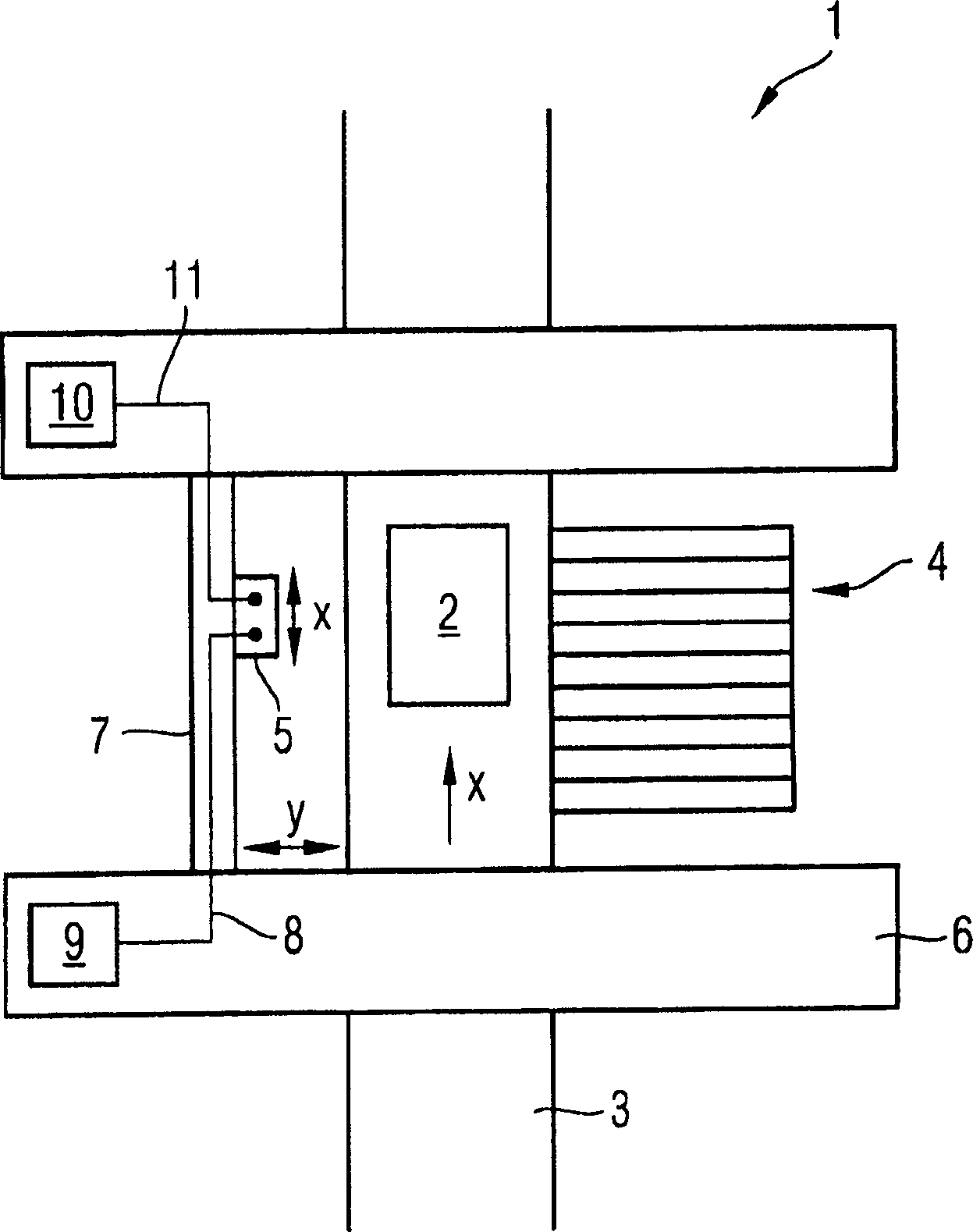
[0021] exist figure 1 An embodiment of an inventive device for manipulating components or an automatic assembly machine 1 for assembling electrical components to a circuit board 2 is schematically shown in FIG. The circuit boards 2 to be assembled are conveyed along the conveying line 3 in the conveying direction (arrow x) to the assembly station, assembled there, and conveyed further. On the part of the conveyor line 3, there is a feed device 4 for supplying electrical components in the feed area. The assembly head 5 is arranged to be travelable between the feeding device 4 and the assembly position by means of a positioning system. The positioning system here comprises two beams 6 of the gantry crane type, which span the conveying line 3 in the form of a bridge, and a longitudinal beam 7 which is movably supported at its ends on the beams 6 and which, for example by means of Due to the linear motor it is possible to travel transversely to the conveying direction (arrow y)....


PUM


Abstract

A device used on operation components, especially automatic assembling machine (1) used to assemble electrical components to the circuit board (2), has at least one grasping module (13) and one regulating electronic device (10). The grasping module mentioned above has a pressure regulating module (17) and a suction device (15) for said maintaining components. The suction inlet (16) of the suction device is linked with the suction port of the pressure regulating module (17) pneumatically. The regulating electronic device (10) and the fluid sensor (27) are linked with the controllable valve (25), so as to control the valve (25) by the throughput of the gas in the suction catheter (24).

Description

technical field [0001] The invention relates to a device for handling components, in particular an automatic assembly machine for assembling electrical components to circuit boards, and to an associated control method. Background technique [0002] In assembly technology, substrates or circuit boards are loaded with electrical components in automated assembly machines. The assembly head of an automatic assembly machine is used here, which can be moved on a plane parallel to the substrate by means of a positioning system and places the pre-picked electrical components on the substrate. The assembly head here usually has one or more gripping units for picking up, holding and setting down the described components. Each gripping unit generally comprises a suction device, the tip of which can be applied with vacuum to hold the component and with compressed air to lay down or blow the component. For this purpose, the gripper tip has a suction opening, which is connected to the c...

Claims


Application Information

Patent Timeline
Patent Type & Authority Applications(China)
IPC IPC(8): H05K13/04H05K3/30
CPCH05K13/0408H05K13/0409
Inventor S·伯格尔
Owner SIEMENS ELECTRONICS ASSEMBLY SYST LLC
Why Eureka
Try Eureka