

Driving device for passage gates or thoroughfare gates and door or gate drives
A driving device and access technology, applied in the directions of roads, roads, turnstiles, etc., can solve the problems of increasing the difficulty, high cost and price of the manufacturer's processing management, and achieve the reduction of wearing parts, the convenience of production management, and the reduction of The effect of manufacturing cost
- Summary
- Abstract
- Description
- Claims
- Application Information
AI Technical Summary
Problems solved by technology
Method used
Image

Examples
Embodiment Construction
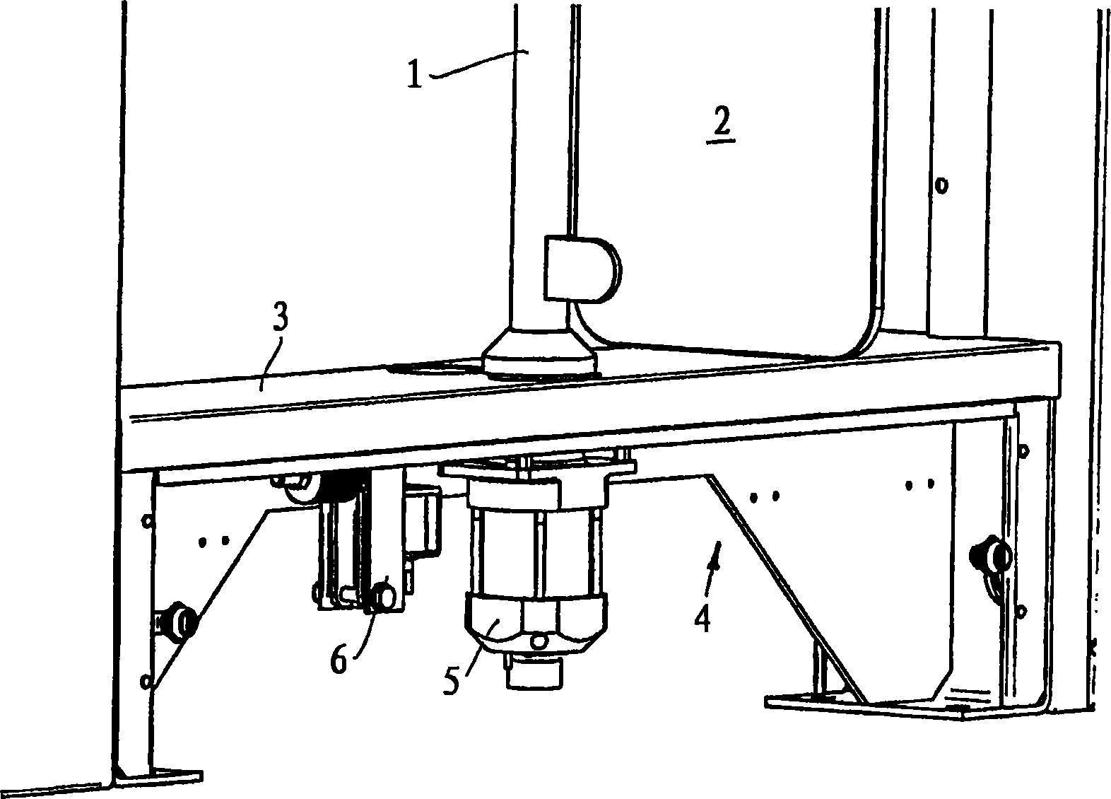
[0018] In the pillar 1 there is a shaft that is not visible in the figure that performs a rotary movement; it passes through the plate 3 of a table-like base 4 and is directly connected to a brushless DC servo motor 5 below the plate 3, that is, without the center. Connect the transmission. A locking unit 6 is provided next to the motor 5 for reliable operation, the locking unit securely fixes the blocking element in its closed position and its open position, and it also allows the motor 5 or the blocking element 2 to stop in any position.
[0019] For all types of barriers, in particular pedestrian barriers, in which the blocking elements have a purely rotational or pendulum movement, it is also conceivable to use a brushless DC servo motor 5 with a servo regulator as a direct drive, i.e. without a transmission in between, also That is to say the output shaft of the DC servo motor 5 is directly connected to the blocking element 2 . The speed and torque of the motor 5 have no...
PUM
 Abstract
Description
Claims
Application Information