Device for cleaning a combing segment in a combing machine

A cleaning and combing technology, which is applied in combing machines, fiber processing, textiles and papermaking, etc. It can solve the problems of changing the speed of the brush roller and affecting the cleaning effect, etc.

Inactive Publication Date: 2006-12-27
MASCHINENFABRIK RIETER AG
View PDF1 Cites 15 Cited by
  • Summary
  • Abstract
  • Description
  • Claims
  • Application Information

AI Technical Summary

Problems solved by technology

[0004] Often the possibility of varying the speed of the brush rollers is sufficient to affect the cleaning action
However, with the known devices it is impossible to adapt exactly and individually to different situations such as: short fiber fraction, degree of soiling of the material, tuft length and structure of the carded portion and the percentage of noil

Method used


Image

  • Device for cleaning a combing segment in a combing machine
  • Device for cleaning a combing segment in a combing machine
  • Device for cleaning a combing segment in a combing machine

Examples


Embodiment Construction

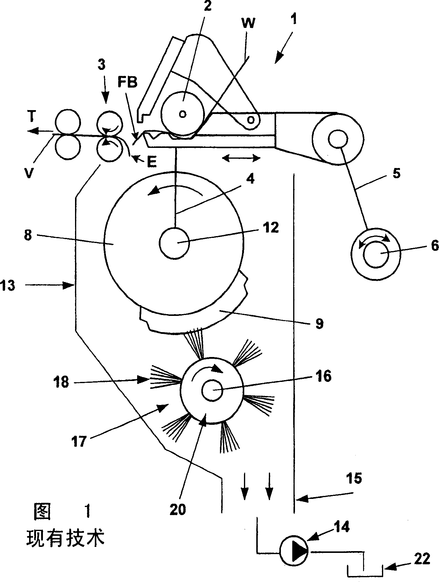
[0036] Fig. 1 is a schematic side view of a combing device of a combing machine. There are actually 8 such combs arranged next to each other. The combing unit contains a nipper unit (called upper nipper for short fibers) which is reciprocated by means of rocker arms 4,5. Rocker arms 4 (only one shown) are rotatably mounted on the circular comb axis 12 and the nipper 1 . A rocker arm 5 , which is rotatably mounted on the rod 1 , is connected in a rotatably fixed manner to a driven nipper shaft 6 . The lap W is fed to a feed drum 2 rotatably mounted inside the nipper 1 . The lap W is unwound by lap rollers, not shown, and is also fixed on lap rollers of the unwinding process, also not shown.

[0037] In the position shown in FIG. 1, the nipper device 1 is open and is in the front position in which the ends FB protruding from the nipper device (referred to as fiber bundles) are laid on the finished On the end E of the nonwoven fabric V, and welded on the end E. The nonwoven ...


PUM


Abstract

In apparatus for cleaning the comb segments of a circular comb in a combing machine, comprising a cleaning roller (17) parallel to and spaced from the round comb and with peripheral cleaning elements (18) temporarily contacting the segments during rotation of the roller, some of the cleaning elements differ from the other cleaning elements in geometrical location, geometrical pattern and/or material.

Description

technical field [0001] The invention relates to a device for cleaning the combing part of a circular comber of a combing machine, which comprises a cleaning roller rotatably mounted at a certain parallel distance from the axis of the circular comber, on the circumference of which cleaning rollers are provided with cleaning rollers. elements, these cleaning elements temporarily come into contact with the comb portion during the rotational movement. Background technique [0002] In a combing machine such as partly shown in EP-A1-564 408, the lap end (also called fiber bundle) provided by the nipper arrangement is rotatably rotated by a circular comb below the nipper arrangement. The combing part of the installation is combed out. During this process, in particular the individual short fibers which are not clamped by the nipper device are combed out of the fiber bundle by the carded portion. In addition, other components such as pollutants, neps and seed impurities are combed...

Claims


Application Information

Patent Timeline
Patent Type & Authority Applications(China)
IPC IPC(8): D01G19/06
CPCD01G19/22
Inventor T·措林格尔W·斯拉维克
Owner MASCHINENFABRIK RIETER AG
Why Eureka
Try Eureka