Low cost energy-consumption shock-dampening method, the related device and its usage method
A low-cost, energy-consuming technology, applied in the direction of earthquake resistance, building components, etc., can solve the problem of low cost and other problems, achieve the effect of reducing the amount of concrete, facilitating construction, and improving seismic performance
- Summary
- Abstract
- Description
- Claims
- Application Information
AI Technical Summary
Problems solved by technology
Method used
Image
Examples
Embodiment 1
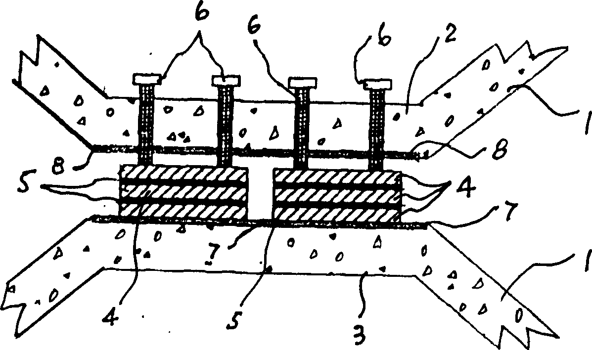
[0034] Example 1: see image 3 . The middle part of the X-shaped reinforced concrete member 1 has an upper platform 2 and a lower platform 3, and there is a space between the two. There are two energy dissipating units, and each dissipating unit is provided with three steel plates 4 and two rubber sheets 5 clamped in the steel plates 4 at intervals. The fastening force applying mechanism of each energy dissipator unit is two bolts 6 vertically passing through the upper platform 2 of the reinforced concrete bar 1 and one end of which can press against the uppermost steel plate 4 . A steel plate 7 is pre-embedded in the lower platform 3 of the reinforced concrete member, and the lowermost steel plate 4 in each energy dissipation unit is directly welded and fastened to the pre-embedded steel plate 4 . 8 in the figure is the embedded steel plate embedded in the upper platform 2, and the bolt 6 also passes through the embedded steel plate 8. In this embodiment, when on-site inst...
Embodiment 2
[0035] Example 2: see Figure 4 . An energy consumer unit is installed, and the energy consumer unit is provided with three steel plates 9 and two rubber sheets 10 clamped between the steel plates 9 . The fastening force applying mechanism of the energy dissipator unit is three bolts 11 that vertically pass through all the steel plates 9 and rubber sheets 10 and can be tightened. A steel plate 12 is pre-embedded in the lower platform 3 of the reinforced concrete member 1, and the extension of a steel plate 9 in the middle of the energy dissipation unit is fastened to the pre-embedded steel plate 12 with a large bolt 12 . 13 in the figure is the pre-embedded steel plate embedded in the upper platform 2, one end of the two connecting steel parts 14 is fastened to the steel plate 9 of the energy dissipation unit, and the other end is welded and fastened to the pre-embedded steel plate 13. In this embodiment, the vertical tightening force is applied to the steel plate and the ru...
Embodiment 3
[0036] Example 3: see Figure 5 . The energy dissipator unit has two upper and lower steel plates 15, a middle steel plate 19, and two rubber sheets 16 respectively clamped between the three steel plates. The fastening force applying mechanism of the energy dissipator unit is four bolts 17 that vertically pass through the upper and lower two steel plates 15 and can be tightened. The extended part of the middle steel plate 19 is provided with two notches, and the two sides of the main body of the energy dissipation unit are also provided with two notches, and correspondingly equipped with four fastening steel plates 18 that can be embedded in the above four notches , one end of each steel plate 18 has a slope. When installing the energy dissipator unit, insert the fastening steel plate 18 into the corresponding notch, with the slopes of the two steel plates 18 facing upwards and the slopes of the two steel plates 18 facing downwards, and respectively connect the top of the sl...
PUM
 Abstract
Description
Claims
Application Information
 - R&D
- Intellectual Property
- Life Sciences
- Materials
- Tech Scout
- Unparalleled Data Quality
- Higher Quality Content
- 60% Fewer Hallucinations
Browse by: Latest US Patents, China's latest patents, Technical Efficacy Thesaurus, Application Domain, Technology Topic, Popular Technical Reports.
© 2025 PatSnap. All rights reserved.Legal|Privacy policy|Modern Slavery Act Transparency Statement|Sitemap|About US| Contact US: help@patsnap.com


