Gantry type self-walking roofbolter

A gantry-type self-anchor technology, which is applied to rotary drilling rigs, bolt installation, percussion drilling, etc., can solve the problems of affecting work efficiency and wasting time

Inactive Publication Date: 2006-12-27
SHANXI DONGHUA MACHINERY
View PDF1 Cites 15 Cited by
  • Summary
  • Abstract
  • Description
  • Claims
  • Application Information

AI Technical Summary

Problems solved by technology

Supporting and excavation work alternately and reciprocatingly, which wastes a lot of time and greatly affects work efficiency, especia

Method used


Image

  • Gantry type self-walking roofbolter
  • Gantry type self-walking roofbolter
  • Gantry type self-walking roofbolter

Examples


Embodiment Construction

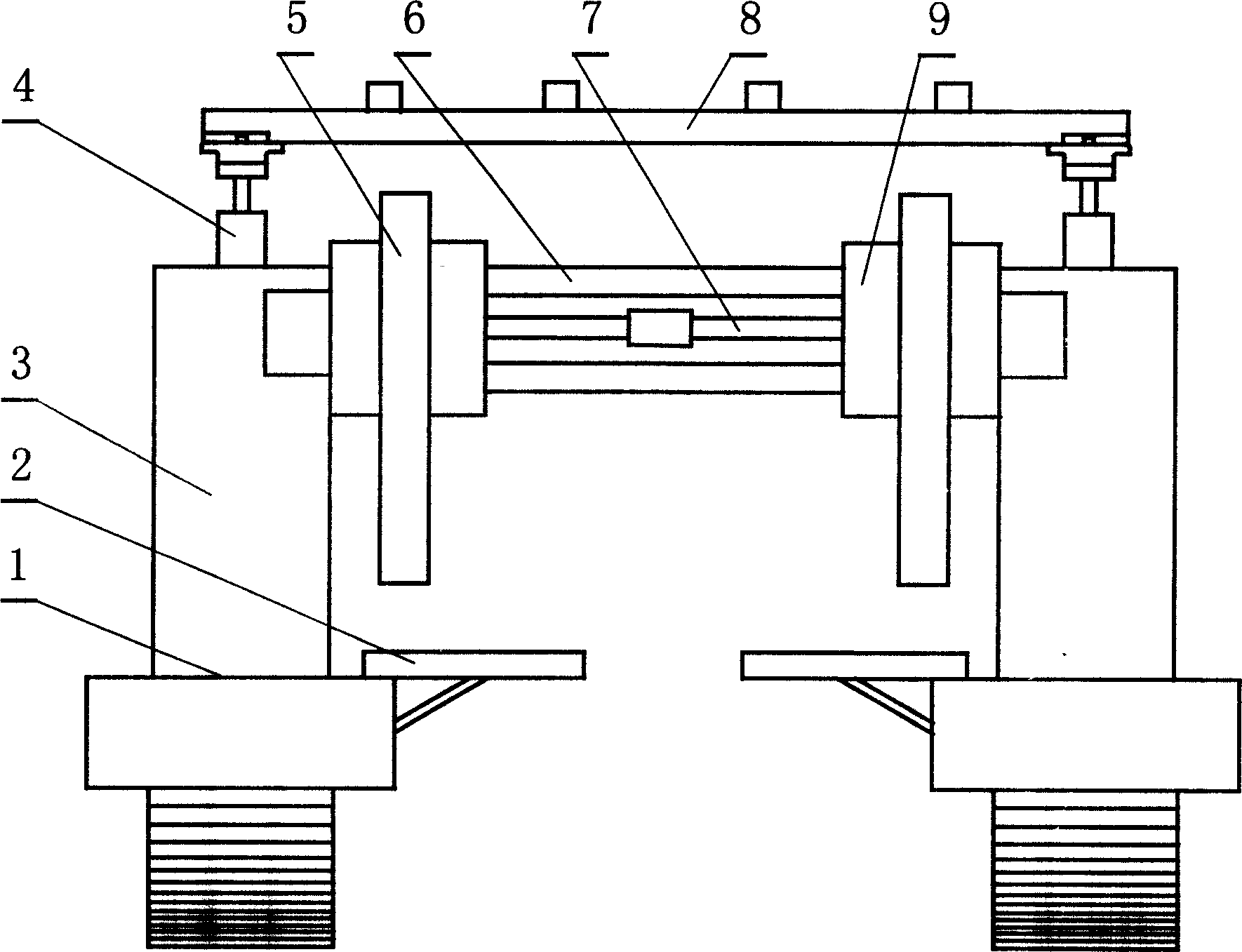
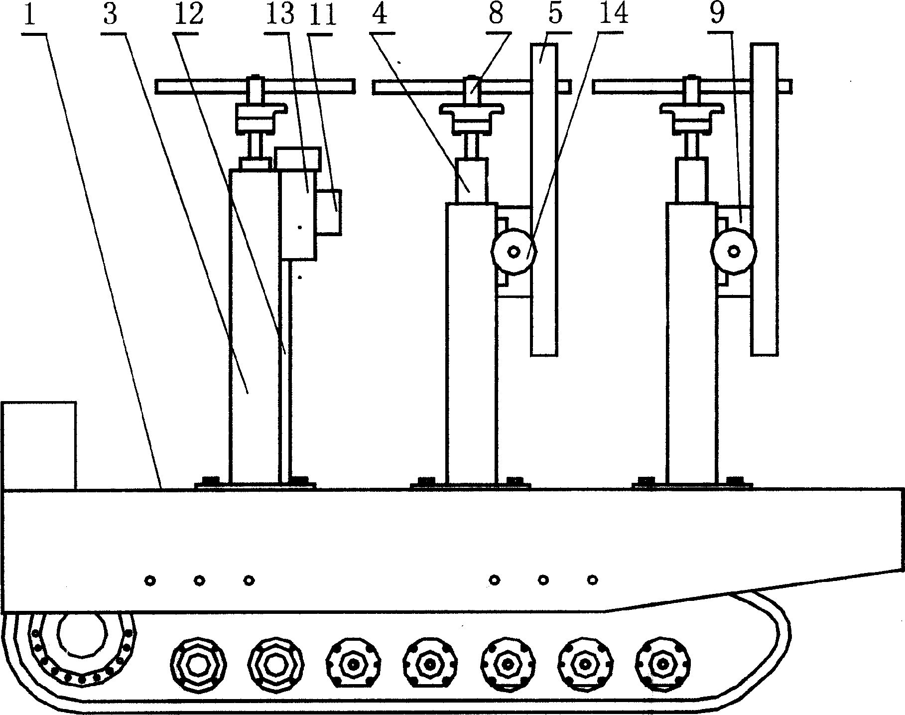
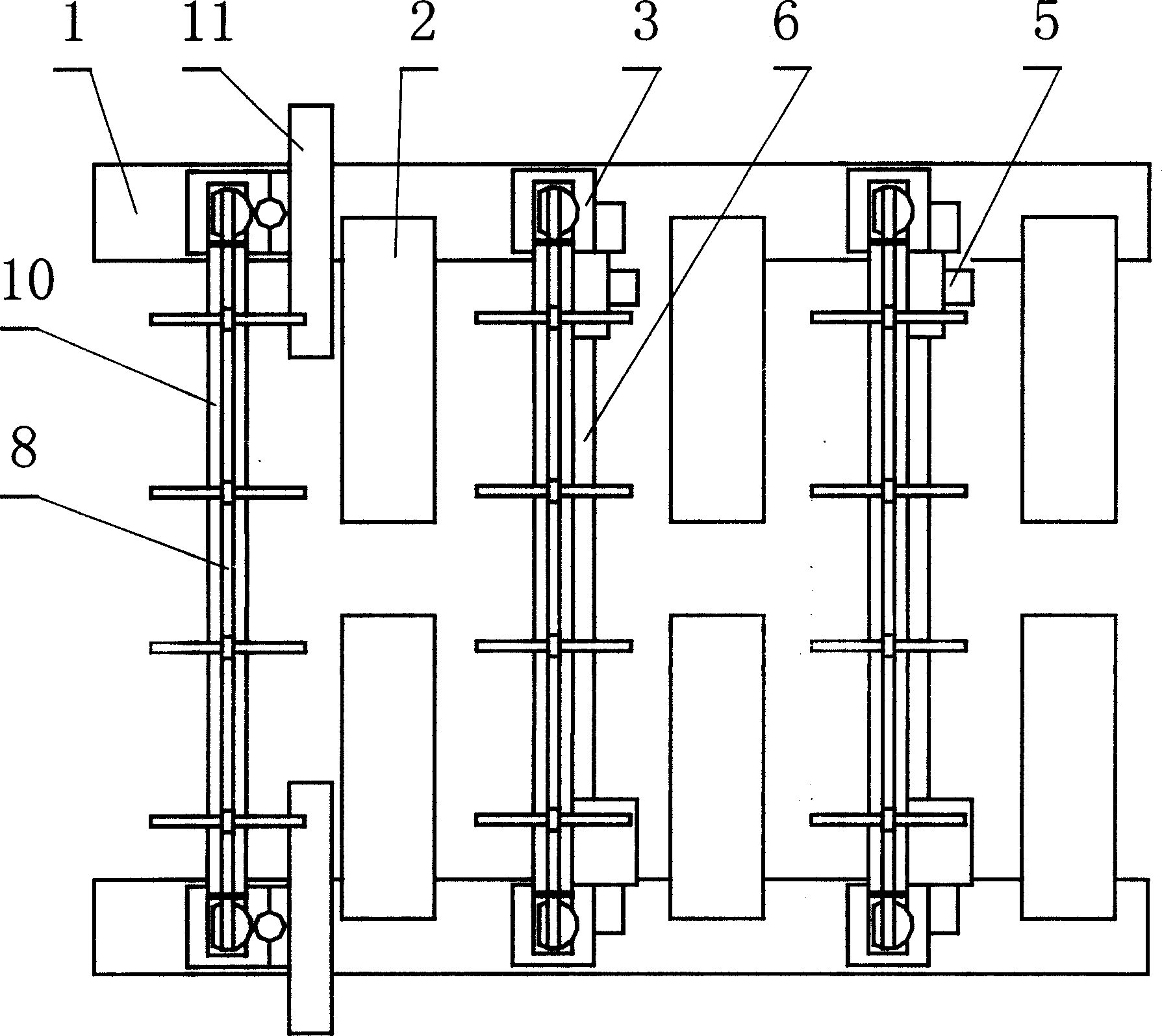
[0018] figure 1 , figure 2 , image 3 As shown, the present invention includes a crawler belt traveling mechanism and a hydraulic system positioned on the crawler belt traveling mechanism, a gantry frame, and a horizontal drilling machine 11 and a longitudinal drilling machine 5 installed on the gantry frame. Described frame is gantry type, and it is made up of two columns 3 and a crossbeam 10 that is fixed on two columns 3. At least one gantry frame straddles the platforms 1 of the two parallel crawler running gears. figure 1 , Figure 4 As shown, the transverse guide rail 6 and the beam screw rod 7 are fixed on the beam 10 of a gantry frame, and the transverse slide plate 9 equipped with the longitudinal drilling machine 5 is set on the transverse guide rail 6, so that the transverse slide plate 9 and the transverse guide rail 6 are slidably matched. Crossbeam screw mandrel 7 engages with the spiral tube engagement on the transverse slide plate 9, and the lateral moveme...


PUM


Abstract

The invention relates to a tunnel constructing device, especially providing an automatic anchor rod driller for supporting the top plate and side wall, wherein said invention is formed by track walking device, frame and the drilling machine mounted on the frame; said invention can not work with tunneller, to cause low working efficiency. The invention is mainly formed by two separated portable frames mounted on the track walking device; the longitudinal and transverse drilling machines are independently mounted on the beam and upright post of portable frame; the tunneller can move at the middle of portable frame, to improve the working efficiency.

Description

Technical field [0001] The invention relates to a tunnel construction machine, in particular to a self-propelled rock bolt drilling machine used in coal mine roadway roof and side support operations. Background technique [0002] At present, large and medium-sized coal mines generally use roadheaders for operations to improve work efficiency. In order to prevent the roadway from collapsing and ensure the safety of construction workers, the top and side of the roadway must be supported. There are many ways to support, and currently the most common way is to support with bolts. The traditional bolt support operation is to use a manual shoulder-mounted drilling rig to drill anchor holes on the top and sides of the roadway, and then install the bolt. This method is time-consuming and labor-intensive, labor-intensive, low-efficiency, and difficult to guarantee construction quality, which greatly affects subsequent excavation operations and has become a bottleneck for increasing...

Claims


Application Information

Patent Timeline
IPC IPC(8): E21B3/00E21D20/00
Inventor 慎高升慎志东张雨樵申俊虎宋翠萍梅静孙河清司天善张棋刘彦生
Owner SHANXI DONGHUA MACHINERY
Why Eureka
Try Eureka