High-gain waveguide trumpet array flat antenna

A flat-panel antenna and high-gain technology, applied in waveguide horns, antennas, antenna arrays, etc., can solve the problems of unfavorable antenna miniaturization, large waveguide antenna size, and difficult processing, and achieve weight reduction, good precision, and reduced manufacturing costs Effect

Inactive Publication Date: 2006-12-27
北京海域天华通信技术有限公司
View PDF0 Cites 32 Cited by
  • Summary
  • Abstract
  • Description
  • Claims
  • Application Information

AI Technical Summary

Problems solved by technology

However, the waveguide antenna also has the disadvantages of large volume and di

Method used


Image

  • High-gain waveguide trumpet array flat antenna
  • High-gain waveguide trumpet array flat antenna
  • High-gain waveguide trumpet array flat antenna

Examples


Embodiment Construction

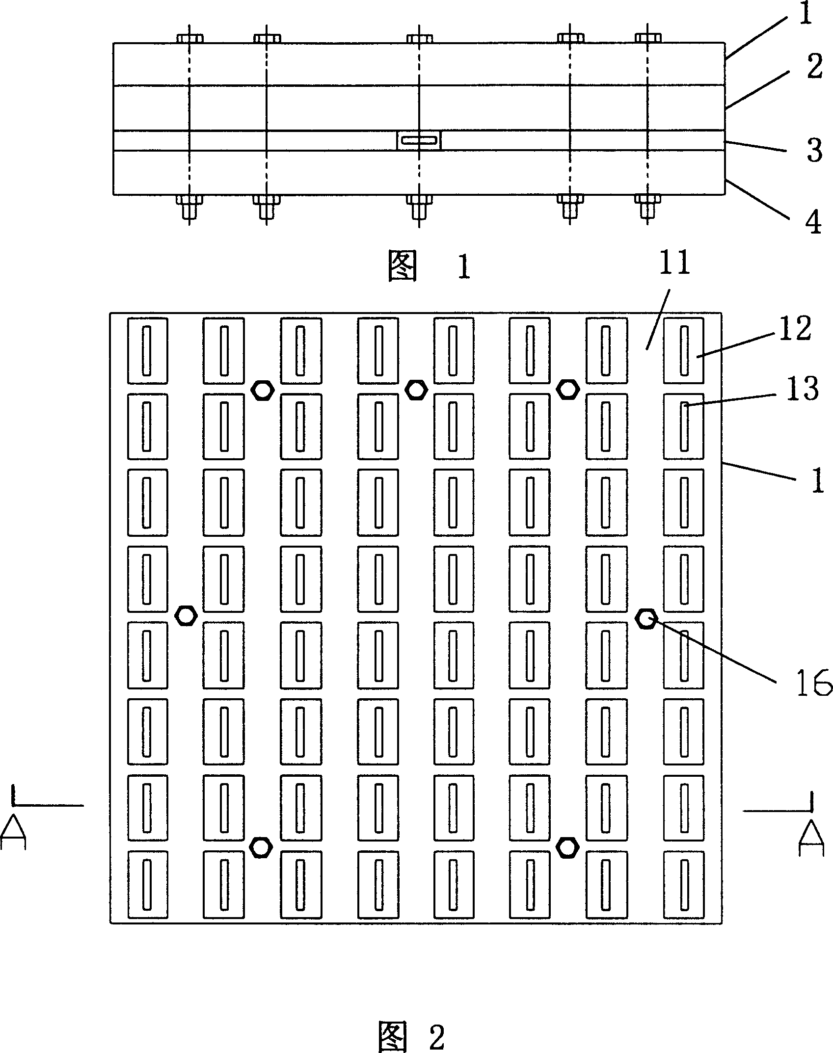
[0036] See Figure 1, Figure 16 , Figure 17 Shown: a high-gain waveguide horn array panel antenna, which includes a top layer conductive plate 1, a middle layer conductive plate 2, a strip line layer conductive plate 3, and a bottom layer conductive plate 4;

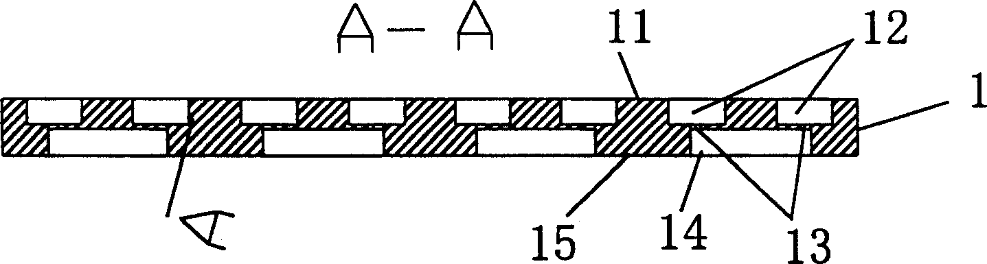
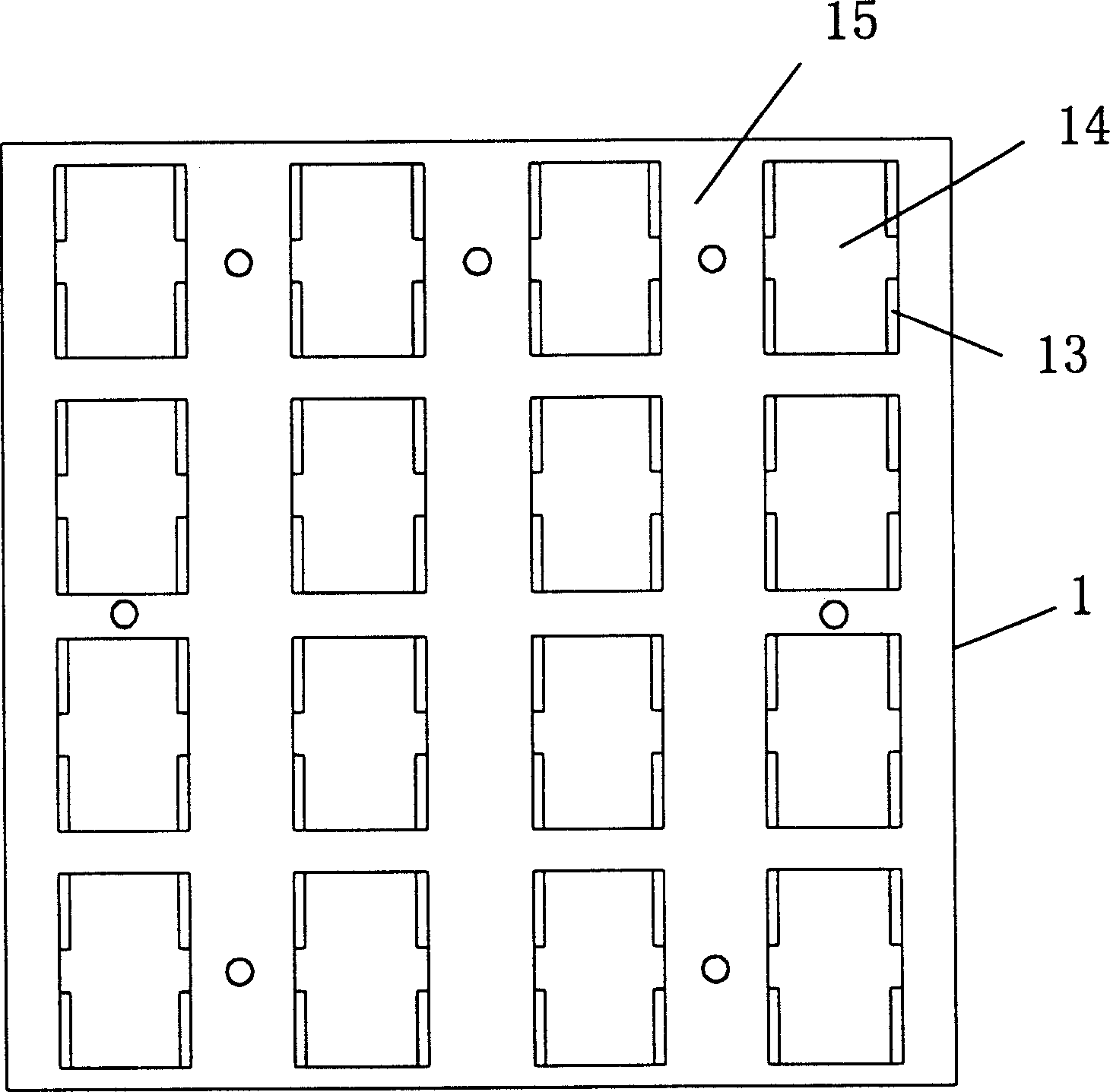
[0037] See Figure 2, image 3 , Figure 4 As shown: the upper surface of the top conductive plate 1 is provided with a plurality of horn holes 12 in an array, and a feeding slot through hole 13 is provided in the middle of the inner bottom of the horn holes 12, and in the lower surface 15 of the top conductive plate 1 The array is provided with a plurality of cavity-shaped conduits 14, and at the four corners of the cavity-shaped conduits 14 there are feeding slot through-holes 13 communicating with the four horn holes;

[0038] see Figure 5 , Figure 6, Figure 7, Figure 8 , Figure 9 As shown: the middle layer conductive plate 2 is arranged at the bottom of the top layer conductive plate 1, and a waveguide corres...


PUM


Abstract

The high-gain waveguide horn array panel antenna comprises: from top to bottom, a top conductive plate with multiple horn holes arranged feeding through hole on bottom on top surface and multiple cavity guide pipes on lower surface, a middle conductive plate with waveguide hole opposite to these in cavity, a thin cable-layer conductive plate, and a bottom conductive plate. This invention can achieve higher precision, reduces weight and cost, and fit wide application.

Description

technical field [0001] The invention relates to the field of panel antenna technology, and is a high-gain waveguide horn array panel antenna Background technique [0002] At present, there are mainly two types of common panel antennas, microstrip antennas and waveguide antennas. The microstrip antenna has the characteristics of small size and light weight. However, due to the characteristics of the dielectric plate in the microwave frequency band, the loss of the final antenna is large and the bandwidth is narrow. Therefore, the manufacture of a high-gain microstrip antenna has many difficulties such as large area and high cost. [0003] The waveguide antenna mainly uses slots or horns as the radiation unit of the antenna. Since the antenna does not use dielectric materials, the loss caused by it is avoided, so it is easy to manufacture high-gain antennas. However, the waveguide antenna also has the disadvantages of large volume and difficult processing, which is not conduc...

Claims


Application Information

Patent Timeline
IPC IPC(8): H01Q13/02H01Q21/00
Inventor 王家齐
Owner 北京海域天华通信技术有限公司
Why Eureka
Try Eureka