Gasoline catalytically converting method and reactor
A reactor and re-catalysis technology, applied in the petroleum industry, hydrocarbon oil treatment, hydrotreating process, etc., can solve problems such as low efficiency, and achieve the effect of improving the ratio of agent to oil, the ratio of large agent to oil, and the low space velocity.
- Summary
- Abstract
- Description
- Claims
- Application Information
AI Technical Summary
Problems solved by technology
Method used
Image

Examples
Embodiment 1
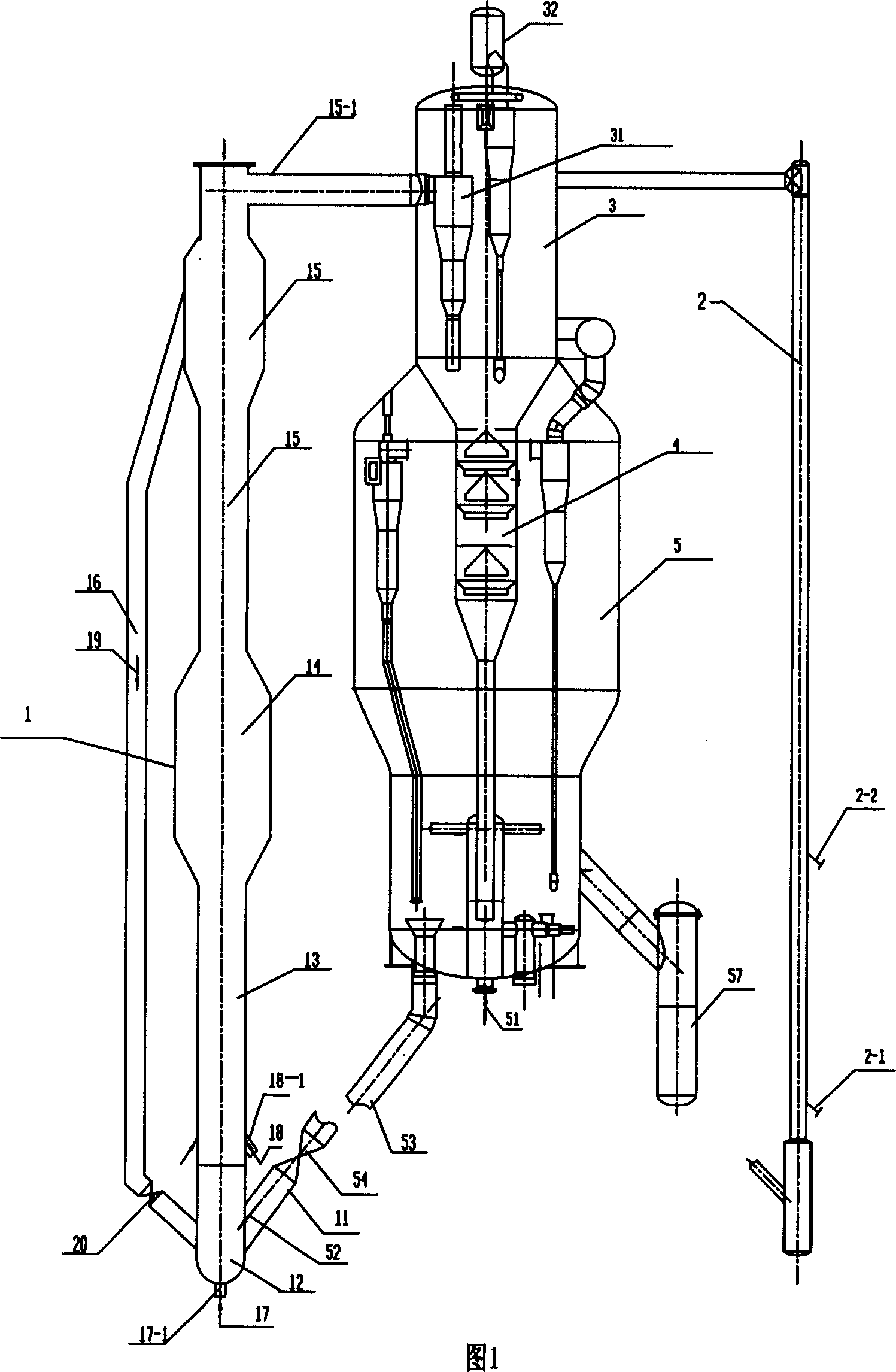
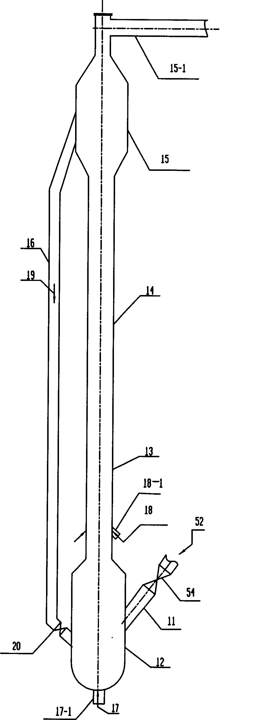
[0029] Embodiment 1, gasoline recatalytic conversion reactor, is made up of catalyst mixing section 12, gasoline gasification section 13, reforming reaction section 14, material lead-out section 15 that penetrate from bottom to top, catalyst mixing section 12 is provided with regenerated catalyst inlet Pipe 11 and lifting medium inlet 17-1, gasoline gasification section 13 is provided with gasoline inlet 18-1, catalyst mixing section 12 and material lead-out section 15 are provided with catalyst return pipe 16, material lead-out section 15 is provided with lead-out pipe 15 -1.
[0030] The anti-re-equipment is composed of raw oil riser reactor 2, gasoline reactor 1, settler 3, stripper 4 and regenerator 5. Hydrocarbon raw materials are subjected to catalytic cracking reaction in feed oil riser reactor 2; gasoline is reacted in gasoline reactor 1.
[0031] In the gasoline reactor 1, the regenerated catalyst 52 from the regeneration standpipe 53 and the slide valve 54 enters th...
Embodiment 2
[0036]Embodiment 2, gasoline recatalytic conversion reactor, is made up of catalyst mixing section 12, gasoline gasification section 13, reforming reaction section 14, material lead-out section 15 that penetrate from bottom to top, catalyst mixing section 12 is provided with regenerated catalyst inlet Pipe 11 and lifting medium inlet 17-1, gasoline gasification section 13 is provided with gasoline inlet 18-1, catalyst mixing section 12 and material lead-out section 15 are provided with catalyst return pipe 16, material lead-out section 15 is provided with lead-out pipe 15 -1. 19 is the backflow catalyst, and 20 is the slide valve. 52 is a regeneration catalyst, 54 is a slide valve, and 11 is a regeneration catalyst inlet pipe.
[0037] The anti-re-equipment is composed of raw oil riser reactor, gasoline reactor, settler, stripper and regenerator. Hydrocarbon feedstock undergoes catalytic cracking reaction in the raw oil riser reactor, and gasoline 18 reacts in the gasoline re...
Embodiment 3
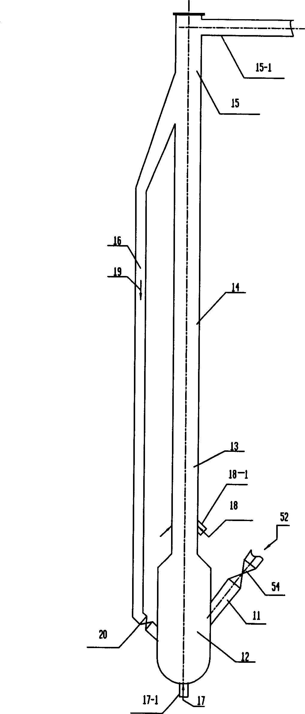
[0042] Embodiment 3, gasoline recatalytic conversion reactor, is made up of catalyst mixing section 12, gasoline gasification section 13, reforming reaction section 14, material lead-out section 15 that penetrate from bottom to top, catalyst mixing section 12 is provided with regenerated catalyst inlet Pipe 11 and lifting gas inlet 17-1, reforming reaction section 14 is provided with gasoline inlet 18-1, is provided with catalyst return pipe 16 between catalyst mixing section 12 and material lead-out section 15, and material lead-out section 15 is provided with lead-out pipe 15 -1. The diameter of the catalyst mixing section 12 is twice the diameter of the gasoline gasification section 13 , the reforming reaction section 14 and the material extraction section 15 . 17 is lift gas, 18 is gasoline, 19 is backflow catalyst, and 20 is slide valve. 52 is a regeneration catalyst, 54 is a slide valve, and 11 is a regeneration catalyst inlet pipe.
PUM
 Abstract
Description
Claims
Application Information
 - R&D
- Intellectual Property
- Life Sciences
- Materials
- Tech Scout
- Unparalleled Data Quality
- Higher Quality Content
- 60% Fewer Hallucinations
Browse by: Latest US Patents, China's latest patents, Technical Efficacy Thesaurus, Application Domain, Technology Topic, Popular Technical Reports.
© 2025 PatSnap. All rights reserved.Legal|Privacy policy|Modern Slavery Act Transparency Statement|Sitemap|About US| Contact US: help@patsnap.com