Method for catalytic conversion of heavy oil and device thereof

A catalytic conversion method and heavy oil technology, applied in catalytic cracking, cracking, petroleum industry, etc., can solve problems such as unfavorable catalytic cracking reaction, reduced catalyst activity, adverse effects of reaction system optimization, etc.

Active Publication Date: 2007-07-04
LUOYANG WEIDA PETROCHEMICAL ENG CO LTD
View PDF5 Cites 0 Cited by
  • Summary
  • Abstract
  • Description
  • Claims
  • Application Information

AI Technical Summary

Problems solved by technology

The disadvantage of this technology is that the regenerated agent and the spent agent are directly mixed, which reduces the activity of the catalyst entering the riser reactor, which is not conducive to the catalytic cracking reaction
[0009] The current heat extraction technology has an adverse effect on the optimization of the reaction system because it only extracts heat in the dense phase section of the regenerator, and the current technology for optimizing the operation of the reaction system has its shortcomings

Method used


Image

  • Method for catalytic conversion of heavy oil and device thereof
  • Method for catalytic conversion of heavy oil and device thereof
  • Method for catalytic conversion of heavy oil and device thereof

Examples


example 1

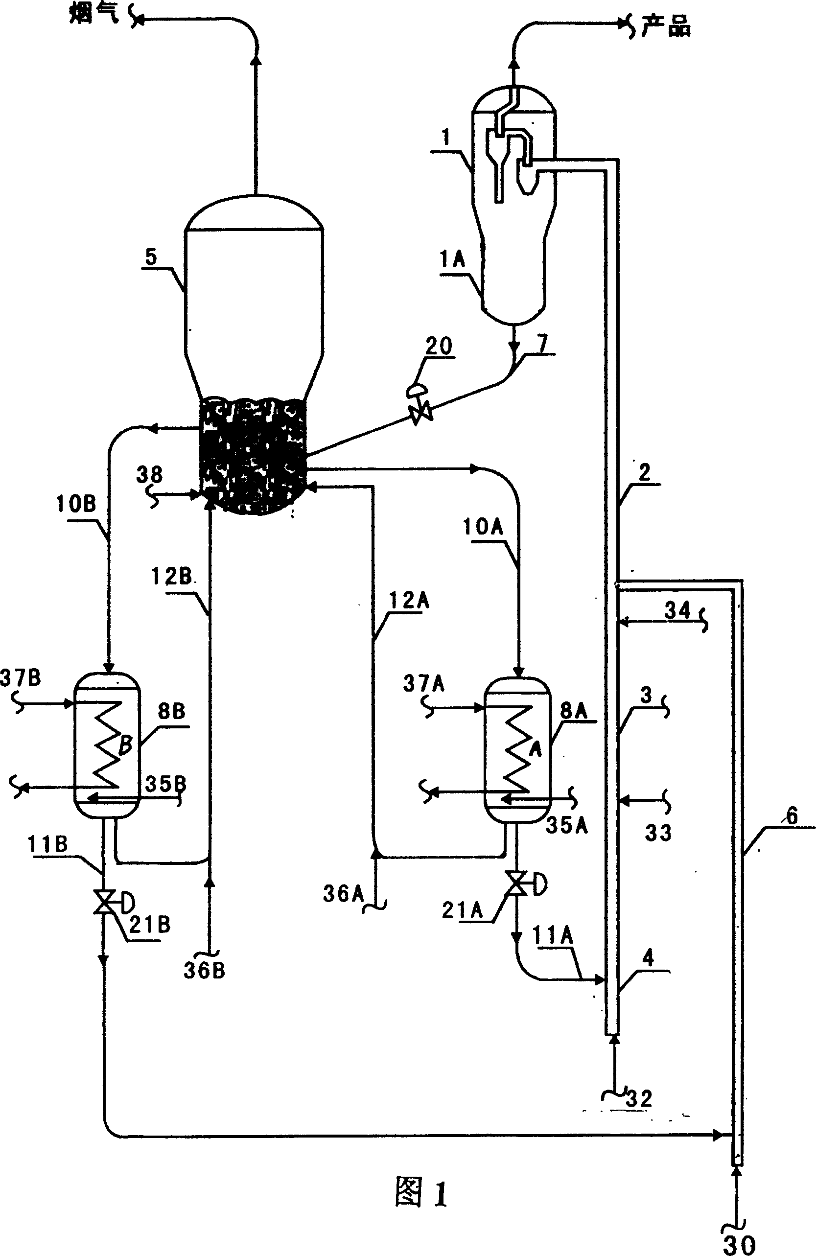
[0140] In order to verify the effect of the present invention, the process flow shown in Figure 1, the process conditions shown in Table 2, the raw materials shown in Table 1, and the GOR-C catalyst produced by the Changling Refinery Catalyst Plant are used. The test results are listed于表3。 In Table 3.

[0141] Logistics

[0142] In Table 2, Scheme A of the prior art adopts conventional heavy oil catalytic cracking technology: the temperature of the regenerator catalyst bed is 700°C, and the reaction temperature is 560°C. The raw material temperature is 240°C, and the agent / oil ratio is 8.0. Therefore, the temperature difference between the regenerant and the raw material is 460°C. Solution A of the prior art has the following shortcomings:

[0143] (1) The temperature of the raw material at 240°C is quite low for the cracking of the residual oil-containing raw material.

[0144] (2) Although the temperature of the regenerator meets the regeneration requirements, the temp...

Embodiment 2

[0149] In order to verify the effect of the present invention, the process flow shown in Fig. 4 is adopted, the process conditions shown in Table 4 and the heavy oil feedstock shown in Table 1 are adopted. The inferior gasoline is catalytically cracked gasoline, and the catalyst is GOR-C. The test results are shown in Table 5.

[0150] In Table 4, the prior art scheme A uses conventional heavy oil catalytic cracking technology: the temperature of the regenerator catalyst bed is 700°C, and the reaction temperature is 560°C. The raw material temperature is 240°C, and the agent / oil ratio is 8.0. Therefore, the temperature difference between the regenerant and the raw material is 460°C. Solution A of the prior art has the following shortcomings:

[0151] (1) The temperature of the raw material at 240°C is quite low for the cracking of the residual oil-containing raw material.

[0152] (2) Although the temperature of the regenerator meets the regeneration requirements, the temperature ...


PUM


Abstract

The invention provides a method of heavy raw material catalytic conversion and the device, comprising: the heavy hydrocarbon raw material passing through the first and second reaction area of the raiser reactor and contacting with catalyst for first reaction and second reaction, the reactants entering into the settler for the separation of catalyst and oil gas, steam stripping the separated catalyst through stripping section and introducing it to the reactivator for carbon burning reactivation, the reactivated catalyst returning to the raiser reactor after cooled or directly to the raiser reactor for reuse. After the heavy oil passing through the device said above, the volume content of olefin decreases by 10~40%, octane value increases 0.5~1 units, sulfur content in petrol decreases 10~30% by weight. After the poor petrol passing through the device said above, the volume content of olefin decreases by 10~60%, octane value increases 0.5~40 units, sulfur content in petrol decreases 10~50% by weight.

Description

Technical field [0001] The invention belongs to the field of catalytic cracking, and particularly relates to a method and a device for catalytic conversion of heavy oil using catalytic cracking. The present invention particularly relates to the catalytic conversion and upgrading of feedstocks containing high-boiling fractions, such as those exceeding 560°C, and inferior gasoline. Background technique [0002] As the quality of crude oil is deteriorating and the tendency to become heavy, the blending ratio of catalytic cracking residues continues to increase, and the quality of gasoline produced by processes such as catalytic cracking, coking, and thermal cracking has become worse. On the one hand, olefins in gasoline are effective components with high octane number. On the other hand, they produce more pollutants during the combustion process and pollute the environment. Although the use of traditional hydrorefining can reduce the olefins in gasoline to a very low level, it great...

Claims


Application Information

Patent Timeline
Patent Type & Authority Patents(China)
IPC IPC(8): C10G55/06C10G11/18
Inventor 李群柱李莉
Owner LUOYANG WEIDA PETROCHEMICAL ENG CO LTD
Why Eureka
Try Eureka