Heat storage type gas radiation pipe burning machine

A radiant tube and burner technology, applied in combustion methods, heat treatment furnaces, heat treatment equipment, etc., can solve the problems of high exhaust smoke temperature of radiant tubes, difficult replacement of igniters, low fuel utilization rate, etc., and achieve high combustion efficiency, The effect of novel technical scheme and long operating life

Inactive Publication Date: 2005-01-26
赵升智
View PDF1 Cites 7 Cited by
  • Summary
  • Abstract
  • Description
  • Claims
  • Application Information

AI Technical Summary

Problems solved by technology

But it just installs an ordinary gas secondary gas nozzle at one end of the radiant tube, and a simple air preheater at the other end; due to the limitation of installation conditions and heating process requirements, the preheating efficiency of this air preheater Very low, the exhaust temperature of the radiant tube is high, and the fuel utilization rate is low
Secondly, the igniter is set at the outlet of the secondary gas nozzle, which is often burned by the high-temperature flame, and it is not easy to replace the igniter on this burner

Method used


Image

  • Heat storage type gas radiation pipe burning machine
  • Heat storage type gas radiation pipe burning machine
  • Heat storage type gas radiation pipe burning machine

Examples


Embodiment Construction

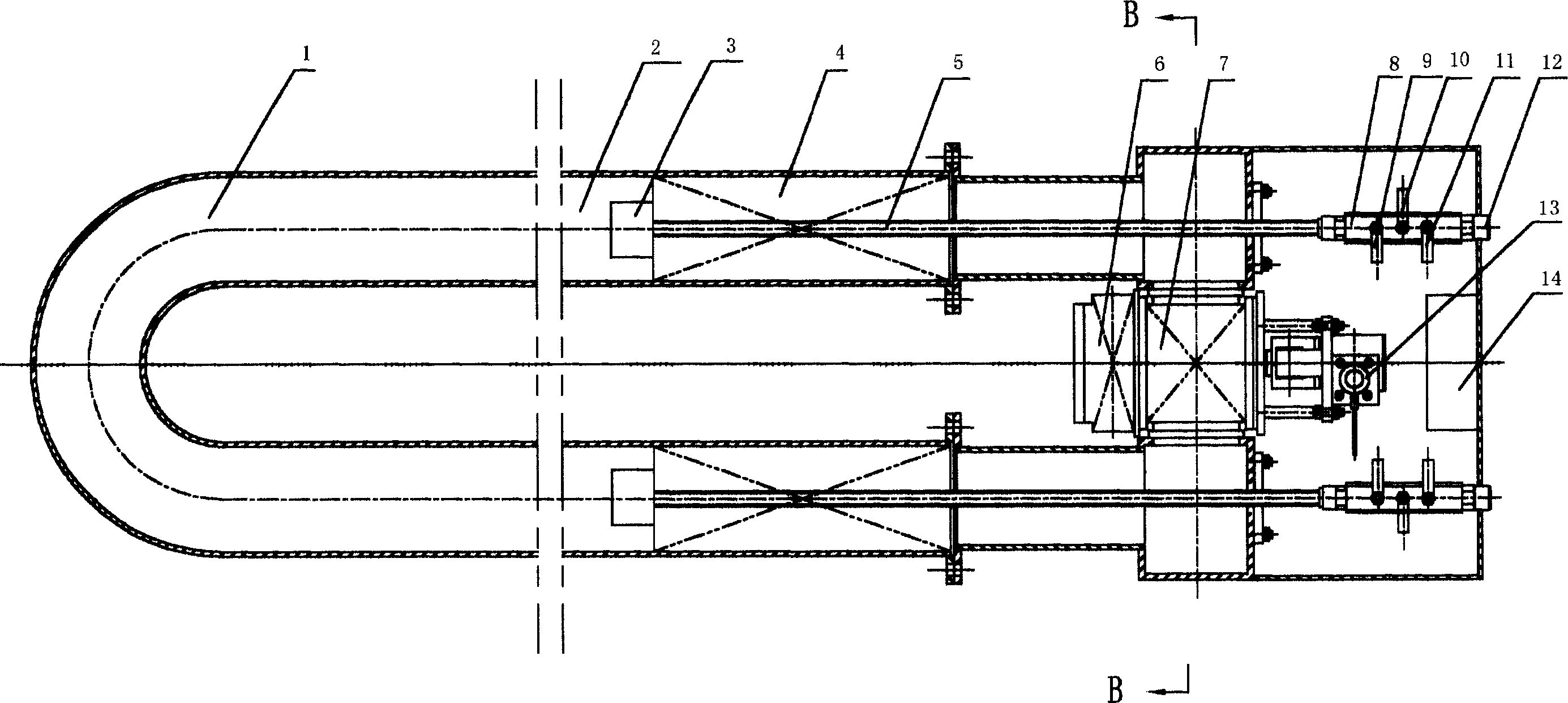
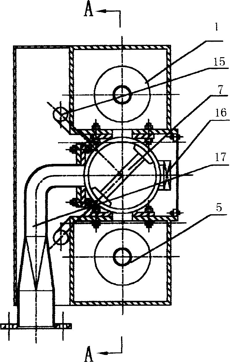
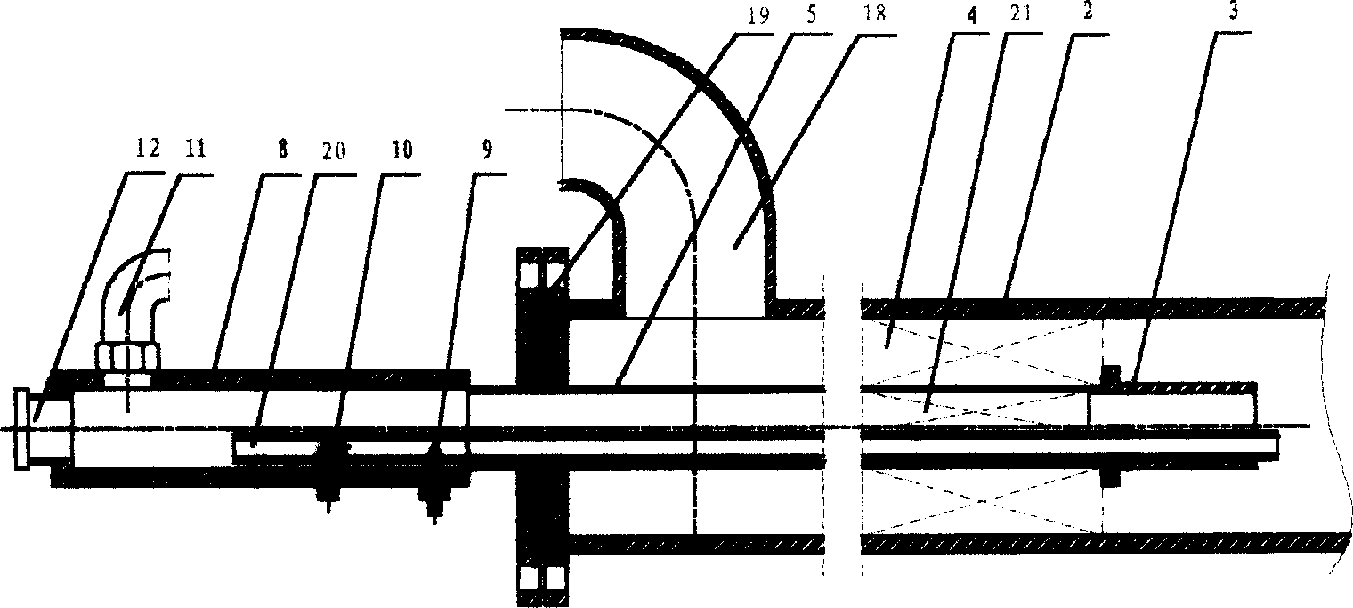
[0021] The specific implementation manners of the present invention will be further described in detail below in conjunction with the accompanying drawings. as attached figure 1 As shown, the main body of the burner is a U-shaped radiant tube, the U-shaped part of the front end is the combustion chamber, and the two rear end straight pipes are equipped with a secondary gas nozzle 3 and a regenerator 4, and the secondary gas nozzles 3 and The regenerators 4 work alternately, and when one end burns, the other end stores heat, so that the temperature field of the entire radiant tube is uniform and the thermal efficiency is high. A gas pipe 5 is arranged in the center of the straight pipe. The gas pipe 5 passes through the center of the storage body 4 and reaches the secondary gas nozzle 3. The rear end of the gas pipe is connected to the remote igniter 8, and the gas inlet 11 is connected to the control valve 6. The straight pipe The air / flue gas pipe at the rear end is connecte...


PUM


Abstract

The invention discloses a heat storage coal gas pipe radiator combustion engine. Belonging to indirect calefaction device, it is adopted on steel, mechanism works' protection atmosphere heat treatment stove and porcelain enamels' heating furnace. The lumen in the front of pipe eradiator in U / W shape is combustion chamber. The secondary gas jet and heat retaining mass are set in two rear straight tube lumens. Gas pipe is set in the center of each straight pipe. Passing through the heat retaining mass, the gas pipe's front end connects with the secondary gas jet. Ignition passage which transfers remote ignition kindling to the secondary gas jet is also set in the center of straight tube. The front end of ignition passage directly reaches to the secondary gas jet and rear end connects with remote igniter. The remote igniter is an airtight cavity in long canister shape. Along ignition kindling progress direction in ignition cavity, ignition gas tube, ignition wind tube and high-pressure ignition head are set in turn. Technical scheme of the invention is novelty, reasonable, simple and effective.

Description

technical field [0001] The invention belongs to a gas heating device for flame insulation heating, which is used in protective atmosphere heat treatment furnaces for iron and steel and mechanical operations, and heating furnaces for enamel and ceramic industries. Background technique [0002] Flame heating is a kind of heating in a special environment. Since there is no open flame during heating, it can only be heated with radiant tubes. The radiation heating developed in the 1980s uses a sleeve-type radiant tube. The main disadvantage of this radiant tube is that its service life is too low. Chinese patent 96218797.6 discloses a "jet flow heat exchange U-shaped gas radiant tube". The radiation area of ​​this U-shaped radiant tube is increased. Under the premise of the same surface heat load, the heating capacity is doubled and the service life is improved. 1.5 times. But it just installs an ordinary gas secondary gas nozzle at one end of the radiant tube, and a simple air...

Claims


Application Information

Patent Timeline
Patent Type & Authority Applications(China)
IPC IPC(8): C21D9/00C23D9/00F23L15/00
CPCY02E20/34
Inventor 赵升智王杰张太富罗才安
Owner 赵升智
Why Eureka
Try Eureka