Coupling equipment for realizing temperature adjustment and stripping of catalytic cracking regenerant
A technology of catalytic cracking and coupled equipment, applied in catalytic cracking, cracking, petroleum industry, etc., can solve the problems of large amount of stripping steam, complex stripper structure, high energy consumption, etc., to improve heat extraction and heat exchange efficiency, Effect of suppressing deactivation effect and enhancing heat transfer efficiency
- Summary
- Abstract
- Description
- Claims
- Application Information
AI Technical Summary
Problems solved by technology
Method used
Image
Examples
Embodiment 1
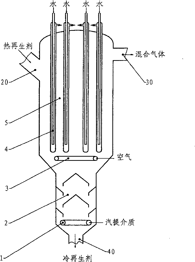
[0043] figure 1 Provided is a schematic diagram of coupling equipment that can realize the tempering and stripping of catalytic cracking regenerant. As shown in the figure, the regenerant temperature-adjusting stripping coupling equipment includes two sections of structure, the upper section is the regenerant temperature-adjusting section 5, and the lower section is the regenerant stripping section or flue gas degassing section 2. The temperature adjustment section 5 has a cylindrical body, in which several heat pipes 4 are arranged as heat exchange components, and the upper part of the cylindrical body is respectively provided with a regeneration agent inlet 20 and a mixed gas outlet 30 . The specific form of the heat-taking pipe 4 can be a commonly used vertical finned tube, squirrel-cage heat exchange tube or nail head heat exchange tube, etc., and can refer to the description and drawings in the above-mentioned Chinese patents 200410083890.3 and 200410080230.X. In the emb...
Embodiment 2
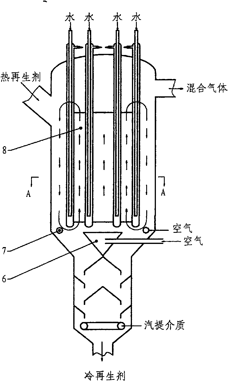
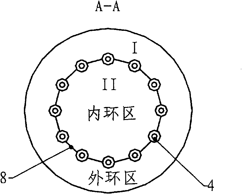
[0049] see figure 2 The difference between the scheme of this embodiment and that of Embodiment 1 is that an annular flow separation sleeve 8 is set in the upper temperature regulation section 5 of the regenerant temperature regulation and stripping coupling equipment, and the cross section of the temperature regulation section 5 is divided into a central circulation area (inner ring area) and outer ring circulation area, image 3 It is a schematic diagram of the cross-sectional structure along the A-direction. The heat pipe is arranged along the wall of the isolation sleeve, and the area ratio of the central circulation zone I to the outer circular circulation zone II can be 0.5-2. Such as figure 2 As shown, two air distributors are arranged at the bottom of the temperature adjustment section 5 to provide fluidizing air for the center ring and the outer ring area respectively. The air distributor 6 in the central area can be an annular tubular distributor or a plate distr...
Embodiment 3
[0053] For the scheme of this embodiment, see Figure 4 , the difference from Example 2 is that two sections of annular partition sleeves 9 and 10 are arranged in the upper temperature regulation section 5 of the regenerant temperature regulation and stripping coupling device, and the two sections of flow partition sleeves are simplified along the temperature regulation section. The axial up and down settings (section structure see image 3 ), leaving an appropriate gap d between them, and making the gap 0.1 to 1.0 times the diameters 9 and 10 of the isolation sleeve. Other parameter settings and work flow can be the same as the second embodiment.
[0054] Experimental studies have shown that the use of two-section flow-blocking sleeve design has a better effect on improving the heat transfer efficiency of the temperature adjustment section.
[0055] Likewise, this embodiment can also be changed to a three-stage or more-stage flow-blocking sleeve structure.
PUM
 Abstract
Description
Claims
Application Information
 - R&D
- Intellectual Property
- Life Sciences
- Materials
- Tech Scout
- Unparalleled Data Quality
- Higher Quality Content
- 60% Fewer Hallucinations
Browse by: Latest US Patents, China's latest patents, Technical Efficacy Thesaurus, Application Domain, Technology Topic, Popular Technical Reports.
© 2025 PatSnap. All rights reserved.Legal|Privacy policy|Modern Slavery Act Transparency Statement|Sitemap|About US| Contact US: help@patsnap.com


