Coupling equipment for realizing temperature adjustment and stripping of catalytic cracking regenerant

A technology of catalytic cracking and coupled equipment, applied in catalytic cracking, cracking, petroleum industry, etc., can solve the problems of large amount of stripping steam, complex stripper structure, high energy consumption, etc., to improve heat extraction and heat exchange efficiency, Effect of suppressing deactivation effect and enhancing heat transfer efficiency

Inactive Publication Date: 2013-06-19
CHINA UNIV OF PETROLEUM (BEIJING)
View PDF2 Cites 2 Cited by
  • Summary
  • Abstract
  • Description
  • Claims
  • Application Information

AI Technical Summary

Problems solved by technology

It can be seen that, in order to realize the cooling of the catalyst while efficiently stripping, the above two prior patents require a large amount of stripping steam for the catalyst, and require the stripping process of the catalyst to run through the process of the catalyst passing through the stripper. The whole process will make the energy consumption of the whole tempering and stripping process too high; and in order to combine the two functions of flue gas stripping and regeneration agent temperature The structure of the device is too complicated, and it is difficult to implement in industrial production

Method used


Image

  • Coupling equipment for realizing temperature adjustment and stripping of catalytic cracking regenerant
  • Coupling equipment for realizing temperature adjustment and stripping of catalytic cracking regenerant
  • Coupling equipment for realizing temperature adjustment and stripping of catalytic cracking regenerant

Examples


Embodiment 1

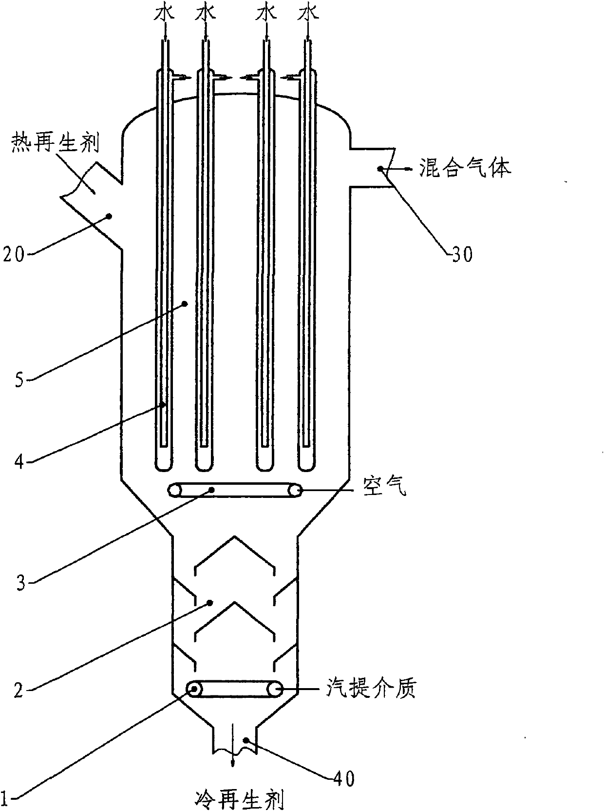
[0043] figure 1 Provided is a schematic diagram of coupling equipment that can realize the tempering and stripping of catalytic cracking regenerant. As shown in the figure, the regenerant temperature-adjusting stripping coupling equipment includes two sections of structure, the upper section is the regenerant temperature-adjusting section 5, and the lower section is the regenerant stripping section or flue gas degassing section 2. The temperature adjustment section 5 has a cylindrical body, in which several heat pipes 4 are arranged as heat exchange components, and the upper part of the cylindrical body is respectively provided with a regeneration agent inlet 20 and a mixed gas outlet 30 . The specific form of the heat-taking pipe 4 can be a commonly used vertical finned tube, squirrel-cage heat exchange tube or nail head heat exchange tube, etc., and can refer to the description and drawings in the above-mentioned Chinese patents 200410083890.3 and 200410080230.X. In the emb...

Embodiment 2

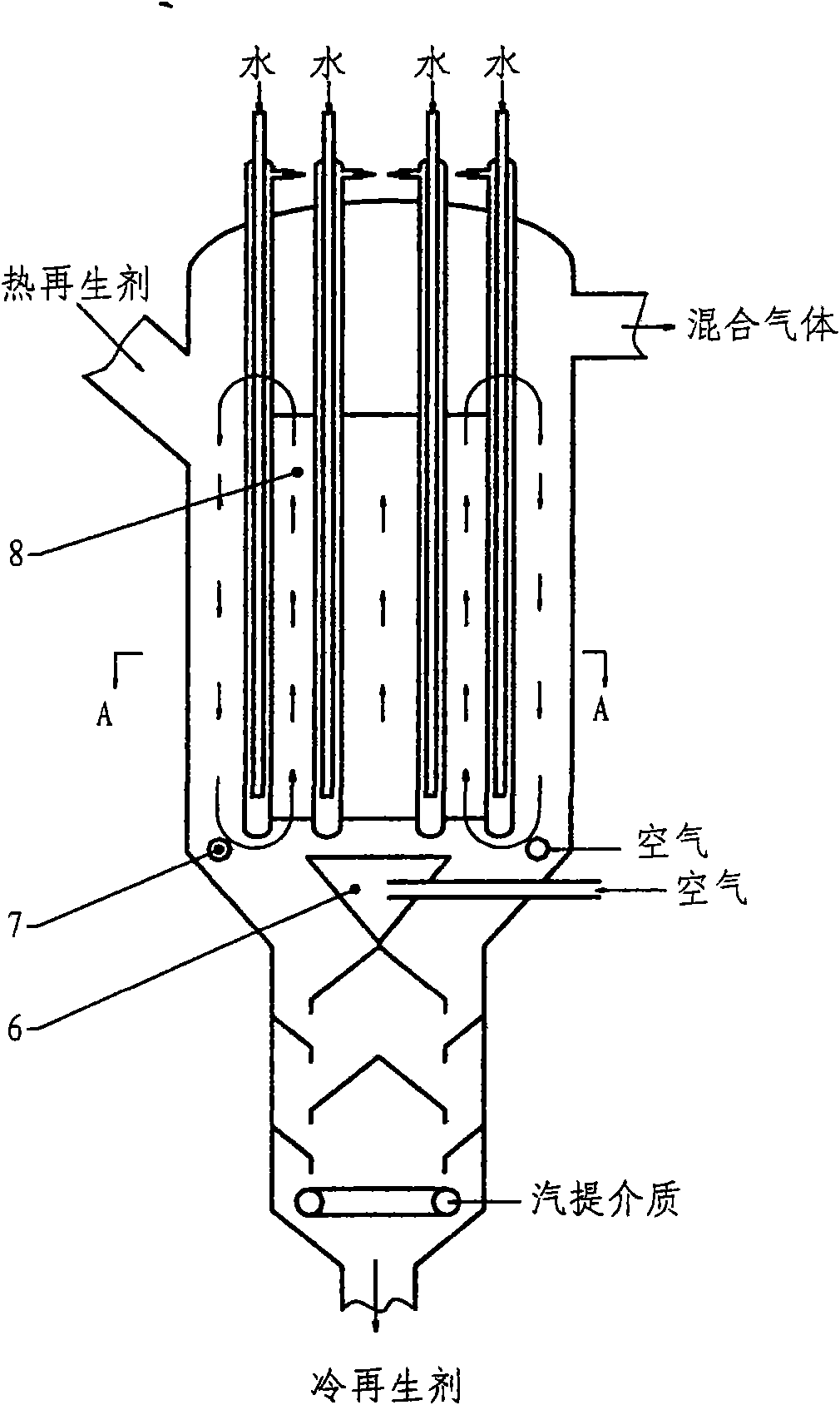
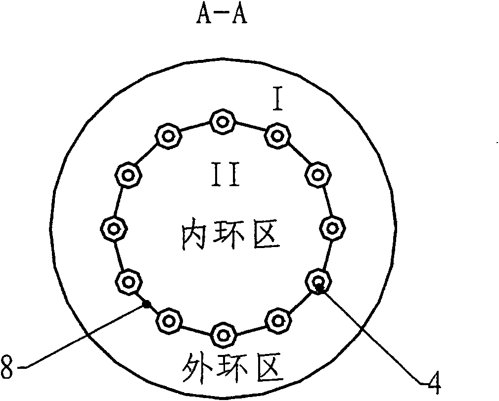
[0049] see figure 2 The difference between the scheme of this embodiment and that of Embodiment 1 is that an annular flow separation sleeve 8 is set in the upper temperature regulation section 5 of the regenerant temperature regulation and stripping coupling equipment, and the cross section of the temperature regulation section 5 is divided into a central circulation area (inner ring area) and outer ring circulation area, image 3 It is a schematic diagram of the cross-sectional structure along the direction of A-A. The heat pipe is arranged along the wall of the isolation sleeve, and the area ratio of the central circulation area I to the outer ring circulation area II can be 0.5-2. like figure 2 As shown, two air distributors are arranged at the bottom of the temperature adjustment section 5 to provide fluidizing air for the center ring and the outer ring area respectively. The air distributor 6 in the central area can be an annular tubular distributor or a plate distrib...

Embodiment 3

[0053] For the scheme of this embodiment, see Figure 4 , the difference from Embodiment 2 is that two sections of annular flow-cutting sleeves 9 and 10 are arranged in the upper temperature-regulating section 5 of the regenerant temperature-adjusting and stripping coupling equipment, and the two-section flow-cutting sleeves are arranged along the temperature-regulating section barrel The axial up and down settings (section structure see image 3 ), leaving an appropriate gap d between them, and making the gap 0.1 to 1.0 times the diameter of the isolation sleeves 9 and 10. Other parameter settings and work flow can be the same as the second embodiment.

[0054] Experimental studies have shown that the use of two-section flow-blocking sleeve design has a better effect on improving the heat transfer efficiency of the temperature adjustment section.

[0055] Likewise, this embodiment can also be changed to a three-stage or more-stage flow-blocking sleeve structure.


PUM

PropertyMeasurementUnit
diameteraaaaaaaaaa
diameteraaaaaaaaaa
diameteraaaaaaaaaa

Abstract

The invention provides coupling equipment for realizing the temperature adjustment and the stripping of catalytic cracking regenerant, which comprises a temperature adjustment section arranged at the upper part and a stripping section arranged at the lower part; the temperature adjustment section is provided with a built-in heat exchange component and at least an air distributor; and the temperature adjustment section extends downwards and reduces the circulation area to form the stripping section. By coupling the stripping area with quite small circulation area at the lower part of the temperature adjustment section, the invention can realize the function of flue gas removal without or only with a small amount of stripping steam, and can best inhibit the inactivation of the regenerant under the steam atmosphere. The coupling equipment of the invention can be arranged in a regenerant circulating pipeline of a catalytic cracker, so that the regenerant directly enters a rise reactor after the temperature is adjusted and the flue gas is removed, thereby not only significantly improving the oil ratio, the regeneration temperature and the raw material pre-heating temperature of the catalytic cracker and facilitating the improvement of product distribution, but also having the function of glue gas removal and reducing the load of a rich gas compressor and the energy consumption of the device.

Description

technical field [0001] The present invention relates to equipment for tempering and stripping a catalytic cracking regenerant in a catalytic cracking reaction, in particular to a coupling equipment for tempering and stripping that integrates the tempering and stripping equipment for a regenerant and using the coupling equipment to The invention relates to a process for implementing temperature regulation and flue gas removal by catalytic cracking regenerant, and the invention belongs to the technical field of petrochemical industry. Background technique [0002] In the petroleum refining industry, the catalytic cracking process is one of the most important petroleum secondary processing processes. In the catalytic cracking process, heavy macromolecular petroleum hydrocarbons are cracked into small Molecular hydrocarbons become the desired light oil products. In my country, catalytic cracking is the most important means of lightening heavy oil. The vast majority of commercia...

Claims


Application Information

Patent Timeline
Patent Type & Authority Patents(China)
IPC IPC(8): C10G11/02
Inventor 张永民刘梦溪卢春喜王祝安孙富伟
Owner CHINA UNIV OF PETROLEUM (BEIJING)
Why Eureka
Try Eureka