Drilling bit for borehole pump pouring large flowing concrete and guniting enlarging footing piling

A large flow, drilling pump technology, applied in the direction of drill bits, sheet pile walls, drilling equipment, etc., can solve the problems of unreasonable force structure and low strength

Inactive Publication Date: 2007-01-03
刘润郊
View PDF1 Cites 7 Cited by
  • Summary
  • Abstract
  • Description
  • Claims
  • Application Information

AI Technical Summary

Problems solved by technology

[0003] The purpose of the present invention is to provide a drill bit for drilling large flow concrete and injecting grout to expand the bottom to form a pile, so as to overcome the defects of low strength and unreasonable stress structure of the existing pile forming drill bit

Method used


Image

  • Drilling bit for borehole pump pouring large flowing concrete and guniting enlarging footing piling
  • Drilling bit for borehole pump pouring large flowing concrete and guniting enlarging footing piling
  • Drilling bit for borehole pump pouring large flowing concrete and guniting enlarging footing piling

Examples


specific Embodiment approach 1

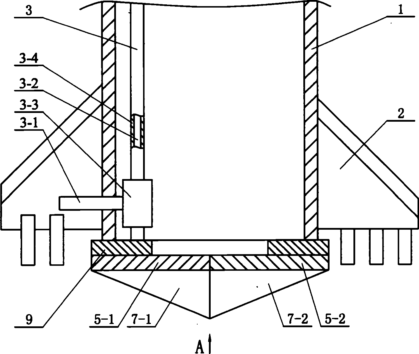
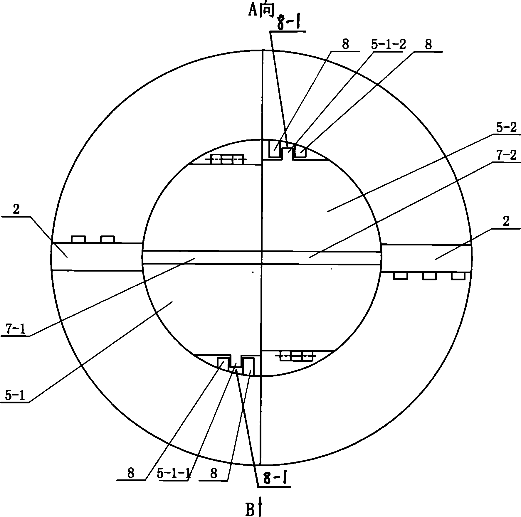
[0005] Specific implementation mode one: the following combination figure 1 and figure 2 This embodiment will be specifically described. This embodiment consists of a cylindrical drill pipe 1, a blade 2 fixed on the outer surface of the drill pipe 1, a shot channel 3 arranged in the drill pipe 1, a left valve plate 5-1, a right valve plate 5-2, a left half The drill point 7-1 and the right half drill point 7-2 are formed, the left valve plate 5-1 is hinged on the bottom end of the drill rod 1 and the left half of the bottom end of the drill rod 1 is closed, and the right valve plate 5-2 is hinged on the drill rod 1. On the bottom of the rod 1 and the right half of the bottom of the drill rod 1 is closed, the left half of the drill point 7-1 is fixed on the lower surface of the left valve plate 5-1, and the right half of the drill point 7-2 is fixed on the right valve plate 5 On the lower surface of -2, the side is that the left half of the drill point 7-1 and the right half...

specific Embodiment approach 2

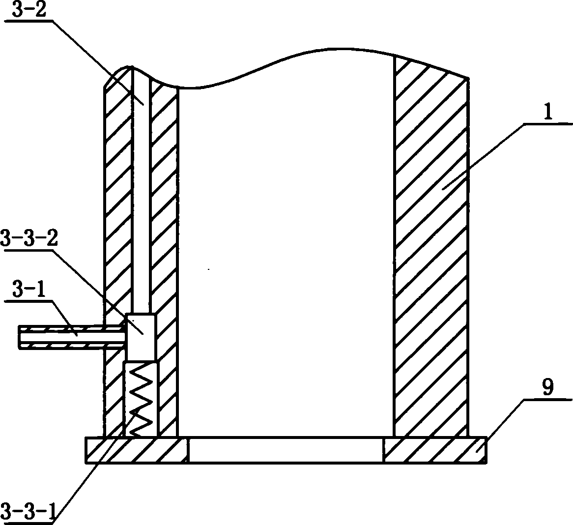
[0006] Specific implementation mode two: the following combination image 3 This embodiment will be specifically described. The difference between this embodiment and Embodiment 1 is: the check valve 3-3 is composed of a spring 3-3-1 and a slider 3-3-2, and the slider 3-3-2 is arranged in the down passage 3-2 , the side surface of the slider 3-3-2 is blocked on one end of the nozzle 3-1, and a spring 3-3-1 is arranged under the slider 3-3-2. During the work of the present embodiment, the descending cement grout makes the slide block 3-3-2 descend, the spring 3-3-1 is compressed, and the cement grout is ejected from the nozzle 3-1. Work ends, because there is no pressure of cement grout, spring 3-3-1 is elongated, and slide block 3-3-2 is blocked an end of nozzle 3-1, and grout can not retrograde. Other composition and connection modes are the same as those in Embodiment 1.

specific Embodiment approach 3

[0007] Specific implementation mode three: the following combination image 3 This embodiment will be specifically described. The difference between this embodiment and the first embodiment is that: the down channel 3 - 2 is opened in the pipe wall of the drill pipe 1 . With such arrangement, the structure is relatively simple and the cost is low.


PUM


Abstract

The present invention discloses a drill bit for drilling, injecting concrete and injecting slurry to enlarge base. It is formed from the following several portions: drill pipe, blade, slurry-injecting channel, left flap, right flap, left-half bit tip and right-half bit tip. Besides, said invention also provides the connection mode of all the above-mentioned portions and its concrete working principle.

Description

Technical field: [0001] The invention relates to a drill bit used for drilling holes and pumping concrete for bottom expansion in pile forming construction. Background technique: [0002] At present, around the pile foundation construction, there have been many kinds of drill bits used for auger drilling and pumping concrete into piles, such as: the authorized announcement number is CN2260820Y, and the name is "Pile Drilling Rig for Pumping Concrete Pile" The structure of the drill bit mentioned in the patent: "The drill bit is welded on the wall of the drill pipe head that has not been cut off, and the two sides of the drill tip are equipped with a discharge valve that can be closed; the valve is closed by a rubber band. When the pump is pouring concrete, The two valves were washed away by concrete..." In this structure, the gap between the valve and the drill pipe head is very easy to be stuck by the clay during construction. In addition, even if the valve is opened, the l...

Claims


Application Information

Patent Timeline
Patent Type & Authority Applications(China)
IPC IPC(8): E21B10/00E02D5/36E02D7/22
Inventor 刘润郊
Owner 刘润郊
Why Eureka
Try Eureka