Amorphous alloy strain gauge

A technology of amorphous alloys and strain gauges, which is applied in the direction of force measurement by measuring the change of magnetic properties of materials caused by applied stress. question

Inactive Publication Date: 2007-01-03
HUAIHAI INST OF TECH
View PDF0 Cites 8 Cited by
  • Summary
  • Abstract
  • Description
  • Claims
  • Application Information

AI Technical Summary

Problems solved by technology

Resistance strain gauge is a common technology for measuring physical quantities such as strain, load, tension, and pressure at present, but there are also some shortcomings: the relationship between the resist

Method used


Image

  • Amorphous alloy strain gauge
  • Amorphous alloy strain gauge
  • Amorphous alloy strain gauge

Examples


Embodiment Construction

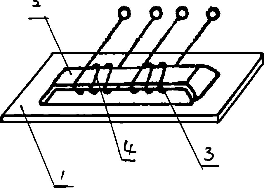
[0008] An amorphous alloy strain gauge, the middle part of the amorphous alloy thin strip 1 protrudes to one side to form an arch bridge-shaped magnetic pole 2, the bridge surface of the magnetic pole 2 is arranged parallel to the main body of the amorphous alloy thin strip 1, and the magnetic pole 2 protrudes The height is h, 0


PUM

PropertyMeasurementUnit
Number of turnsaaaaaaaaaa

Abstract

The middle of amorphous alloy thin strip heaves to one side and forms arch bridge type magnetic pole of a kind of amorphous alloy strain gauge. The bridge of magnetic pole parallel winds along the body of amorphous alloy thin strip and the height of heave is h, 0<h<0.5mm.There are excitation loop and measure loop enlace on the pole side by side and the magnetic field intensity is 0.01-0.05A/mm of the excitation loop. The amorphous alloy strain gauge adheres strongly on surface to measuring material so it takes distortion with measuring work piece along the portrait at the same time. It arouses the change of iron core magnetism conductance and inductance value to finish the test of piece. It utilizes well soft magnetism characteristic and steady temperature capability of amorphous alloy, so it is fit for testing tiny force and displacement with high testing sensitivity. Its temperature error is small and testing circuit is easy to be used in abominable condition with long using life.

Description

technical field [0001] The invention relates to a device for measuring mechanical stress, in particular to an amorphous alloy strain gauge. Background technique [0002] There are many techniques and methods for measuring stress. Similar to non-golden alloy strain gauges are resistance strain gauges, also known as resistance strain gauges. The working principle of resistance strain gauges is based on its strain effect. When using strain gauges to measure component stress or strain, the resistance strain gauge is pasted on the surface of the measured component, and the strain gauge and the part deform together. Since the size and resistivity of the metal wire in the sheet change, the resistance value of the metal wire also changes. The strain or stress can be obtained by measuring the change of the resistance value through the measuring circuit (resistance strain gauge). Resistance strain gauge is a common technology for measuring physical quantities suc...

Claims


Application Information

Patent Timeline
IPC IPC(8): G01L1/12
Inventor 石延平
Owner HUAIHAI INST OF TECH
Why Eureka
Try Eureka