Liquid-filling compressing method for testing metal deformation flow

A technology of metal deformation and compression method, which is applied in the field of inspection, can solve the problems that the stress state of the deformed body cannot be directly given, and the influence of metal deformation and flow cannot be studied, so as to achieve the effect of a reliable inspection method

Inactive Publication Date: 2007-01-03
HARBIN INST OF TECH
View PDF0 Cites 3 Cited by
  • Summary
  • Abstract
  • Description
  • Claims
  • Application Information

AI Technical Summary

Problems solved by technology

However, most of the current process inspection methods can only analyze and predict the shape and defects of the blank, and cannot directly give the stress state inside the deformed body, so it is impossible to study the influence of stress and stress field on the metal deformation flow

Method used


Image

  • Liquid-filling compressing method for testing metal deformation flow
  • Liquid-filling compressing method for testing metal deformation flow
  • Liquid-filling compressing method for testing metal deformation flow

Examples


specific Embodiment approach 1

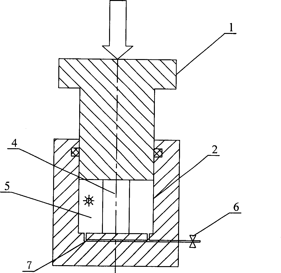
[0012] Specific implementation mode one: combine figure 1 , figure 2 , image 3 , Figure 4 Illustrate this embodiment, its inspection process comprises the following steps:

[0013] Step 1: Record the raw data of the cylindrical sample 4;

[0014] Step 2: Put the cylindrical sample 4 into the liquid-filled chamber 2;

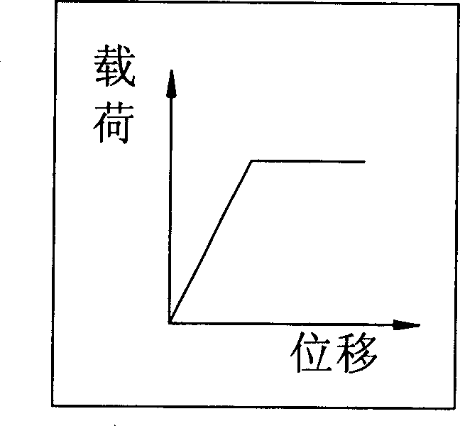
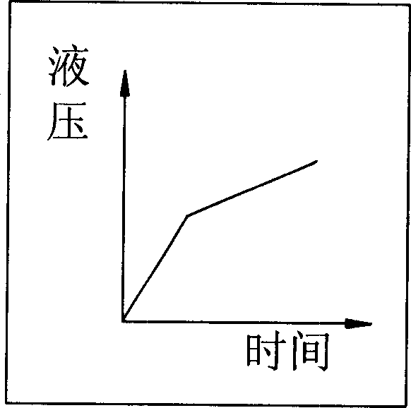
[0015] Step 3: The punch 1 is pressed down, so that the cylindrical sample 4 in the liquid-filled chamber 2 receives the axial principal stress, and at the same time, the high-pressure medium 5 around the cylindrical sample 4 in the liquid-filled chamber 2 is also punched. The volume change brought about by the pressing down of the head 1 causes the hydraulic pressure to change, and the hydraulic pressure is adjusted so that any point in the cylindrical sample 4 always obtains the same transverse principal stress during the pressing down process, reaching the pre-designed hydraulic pressure and press load, making the cylindrical sample 4 compressively def...

specific Embodiment approach 2

[0018] Specific implementation mode two: in conjunction with Fig. 5, Figure 6 , Figure 7 , Fig. 8 illustrates the present embodiment, and its inspection process comprises the following steps:

[0019] Step 1: Record the raw data of the annular sample 3;

[0020] Step 2: Put the circular sample 3 into the middle of the liquid-filled chamber 2;

[0021] Step 3: The punch 1 is pressed down, so that the annular sample 3 in the liquid-filled chamber 2 obtains the axial principal stress, and at the same time, the high-pressure medium 5 around the annular sample 3 in the liquid-filled chamber 2 also The volume change caused by the pressing of the punch 1 causes the hydraulic pressure to change, and the hydraulic pressure is adjusted so that any point in the annular sample 3 can always get the same transverse principal stress during the pressing process, reaching the pre-designed hydraulic pressure and pressure. machine load, so that the annular sample 3 is compressed and deforme...

specific Embodiment approach 3

[0024] Specific implementation mode three: combination figure 1 , figure 2 , image 3 , Figure 4 This embodiment is described. The difference between this embodiment and the first embodiment is that the adjustment of the hydraulic pressure in the third step is to use the pipeline 7, the control valve 6 and the external hydraulic control equipment to adjust the hydraulic pressure of the high-pressure medium 5 . Other steps are the same as in the first embodiment.


PUM


Abstract

One test method for testing the liquid filling compress method when metal distorts and flows to control the stress field formed by metal and to observe and study the behavior of metal distortion and flowing in the beforehand designed stress field. The first step is to record sample originality data. The second is putting the sample into liquid filling room. The third is pressing drift pin and making axial main press on the sample in the liquid filling room, and at the same time changing the volume of high press medium in the liquid filling room to affect the liquid press. Change the liquid press to get the needed main press of landscape orientation according to the beforehand designed liquid press and the load of press machine and the sample compresses and distorts then record data. The forth is repeating the second and third one by testing different liquid press and load of press machine and recording the data. The fifth is using this method to analyze the data to get the relationship between stress and metal distortion and flowing.

Description

technical field [0001] The invention relates to an inspection method, in particular to a liquid-filled compression method for inspecting metal deformation flow. Background technique [0002] There are three main methods for studying the deformation and flow laws of metals in the plastic forming process: 1) physical simulation method; 2) numerical simulation method; 3) process inspection method. In the physical simulation method, plastic clay, photoplastic materials, lead samples, etc. are usually used as substitute materials for the actual metal material. The difference in physical properties between the substitute material and the real metal material causes errors in the simulation results, thus making the physical simulation method difficult. Application is limited. With the development and progress of nonlinear finite element, the numerical simulation method of metal plastic forming process has gradually become the main research method. However, for the complex metal pl...

Claims


Application Information

Patent Timeline
Patent Type & Authority Applications(China)
IPC IPC(8): G01N3/28G01N3/12
Inventor 苑世剑何祝斌
Owner HARBIN INST OF TECH
Why Eureka
Try Eureka