Optical splitter and passive optical network loop system

A technology of passive optical network and optical splitting device, which is applied in the field of passive optical network networking

Inactive Publication Date: 2007-01-03
HUAWEI TECH CO LTD
View PDF0 Cites 19 Cited by
  • Summary
  • Abstract
  • Description
  • Claims
  • Application Information

AI Technical Summary

Problems solved by technology

[0010] The invention provides an optical splitting device and a passive optical network loop system to solve the problem in the prior art that an

Method used


Image

  • Optical splitter and passive optical network loop system
  • Optical splitter and passive optical network loop system
  • Optical splitter and passive optical network loop system

Examples


Embodiment Construction

[0037] The present invention will be described in further detail below in conjunction with the accompanying drawings.

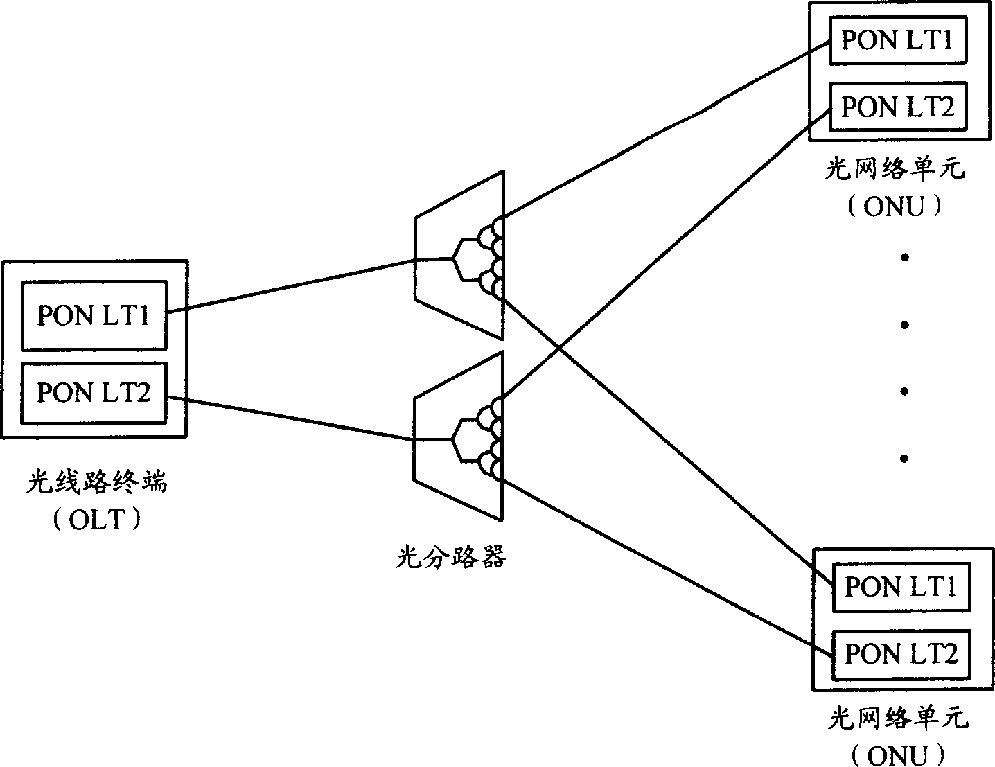
[0038] Figure 6 Shown is a schematic diagram of the structure of the PON loop system of the present invention, and its structure is mainly composed of two logically independent OLTs, a number of ONUs, a number of optical splitting devices with bidirectional optical splitting functions corresponding to the ONUs, and a ring-shaped Composed of at least one optical fiber. In this PON loop system, two logically independent OLTs are connected to each other and can communicate. The OLT and several optical splitting devices are sequentially connected to form a ring through optical fibers. corresponding connection. The two logically independent OLTs may be one OLT physical device with two line terminal modules inside, or two OLT physical devices with one line terminal module inside each.

[0039] The PON loop system of the present invention has no limit to the numb...


PUM


Abstract

This invention discloses a light-splitting device and a passive optical network ring system, in which, the passive optical network ring system includes a primary and a standby optical circuit terminals independent logically and several optical network units and several light splitting devices with two-way splitting function corresponding to the optical network units one by one, the two optical circuit terminals independent logically and the light splitting devices are connected to a ring net by fibers and connected correspondingly. When the device is used to access said optical network unit into the passive optical network ring system, there is not limit to the port number of the network unit, so it can access more terminal users at the same time.

Description

technical field [0001] The invention relates to a passive optical network networking technology, in particular to a light splitting device and a passive optical network loop system. Background technique [0002] In the increasingly large-scale broadband access network, most of the existing local area networks run on the 100Mbit / s network, and many large-scale commercial companies are transitioning to Gigabit Ethernet. At present, the bandwidth capacity of the core network of the metropolitan area and the edge network of the metropolitan area is very abundant, which causes a serious bandwidth bottleneck in the access network. Compared with cable transmission, optical fiber transmission has the advantages of large capacity, low loss, and strong anti-electromagnetic interference capability. Therefore, as the cost of optical fiber transmission gradually decreases, the development of optical fiber in the access network is an inevitable development trend. [0003] PON (Passive Op...

Claims


Application Information

Patent Timeline
IPC IPC(8): H04J14/02H04J3/08
Inventor 杜涌
Owner HUAWEI TECH CO LTD
Why Eureka
Try Eureka