

Heat exchanger and cleaning device with the same
A technology for cleaning devices and heat exchangers, which is applied to water supply devices, water heaters, fluid heaters, etc., can solve the problems of clogging of cleaning nozzles, difficulty in miniaturizing heat exchangers, and difficulty in miniaturizing sanitary cleaning devices, and achieves improved performance. Heat transfer efficiency, reducing the adhesion of impurities, preventing or reducing the effect of adhesion
- Summary
- Abstract
- Description
- Claims
- Application Information
AI Technical Summary
Problems solved by technology
Method used
Image

Examples
Embodiment Construction
[0201] Embodiments of the present invention will be described below with reference to the drawings. However, the present invention is not limited to these embodiments.
[0202] (first embodiment)
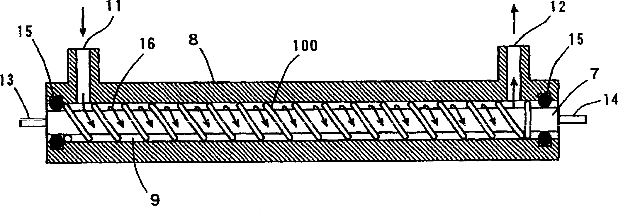
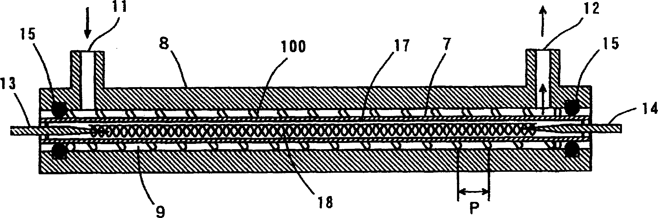
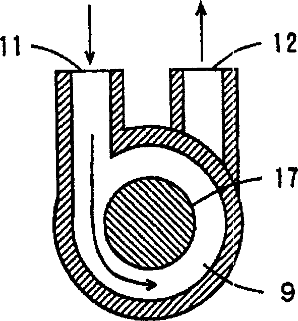
[0203] figure 1 and figure 2 is an axial sectional view of the heat exchanger in the first embodiment of the present invention, figure 1 Indicates the section of the shell and the side of the armored heater, figure 2 Indicates the cross-section of the shell and armored heater. image 3 yes figure 1 and figure 2 Cross-sectional view of the heat exchanger in .
[0204] exist figure 1 Among them, the heat exchanger is composed of a substantially cylindrical sheath heater 7 , a substantially cylindrical casing 8 and a helical spring 100 . The sheath heater 7 is a heating element for heating water as a fluid, and is accommodated in the case 8 . The casing 8 has a hollow with a circular or elliptical cross section, and is provided to surround the outer periphery of the sh...
PUM
 Abstract
Description
Claims
Application Information