Backing radar device without control box

A reversing radar, no control technology, applied in the direction of measuring device, sound wave re-radiation, radio wave measurement system, etc., can solve the problems of easy interference of data lines, inability to test reversing radar, inconvenient installation and detection operations, etc., reaching a length of Shorten, reduce the cost of wire rods, and reduce the effect of the test process

Active Publication Date: 2007-01-10
COLIGEN CHINA
View PDF0 Cites 25 Cited by
  • Summary
  • Abstract
  • Description
  • Claims
  • Application Information

AI Technical Summary

Problems solved by technology

[0004] exist Figure 4 Among them, the connection cables between each ultrasonic sensor 81-84 and the control box 80 include at least a power signal line and a bidirectional data transmission line, so each ultrasonic sensor 81-84 must be connected to the control box through a four-core cable respectively. 80 connection, and when the above connection method is adopted, because the control box 80 is installed in the vehicle body, the ultrasonic sensors 81-84 are generally installed on the bumper of the vehicle. In this case, the control box 80 and the ultrasonic sensor The length of the cable between devices 81-84 is usually not less than 2.5 meters. In this case, not only the cost of the cable is high, but also the data cable that is too long is likely to cause interference
[0005] On the other hand, problems are also encountered in the installation and detection. When the car factory installs the ultrasonic sensors 81-84, because the control box 80 is installed in the vehicle body, the ultrasonic sensors 81-84 are installed on the bumper. Before the rod is installed on the vehicle body, the reversing radar cannot be tested because the control box 80 and the ultrasonic sensors 81-84 have not been connected. Therefore, the reversing radar can only be tested after the installation of the whole vehicle is completed. The operation is very inconvenient, which is not conducive to the improvement of production efficiency

Method used


Image

  • Backing radar device without control box
  • Backing radar device without control box
  • Backing radar device without control box

Examples


Embodiment Construction

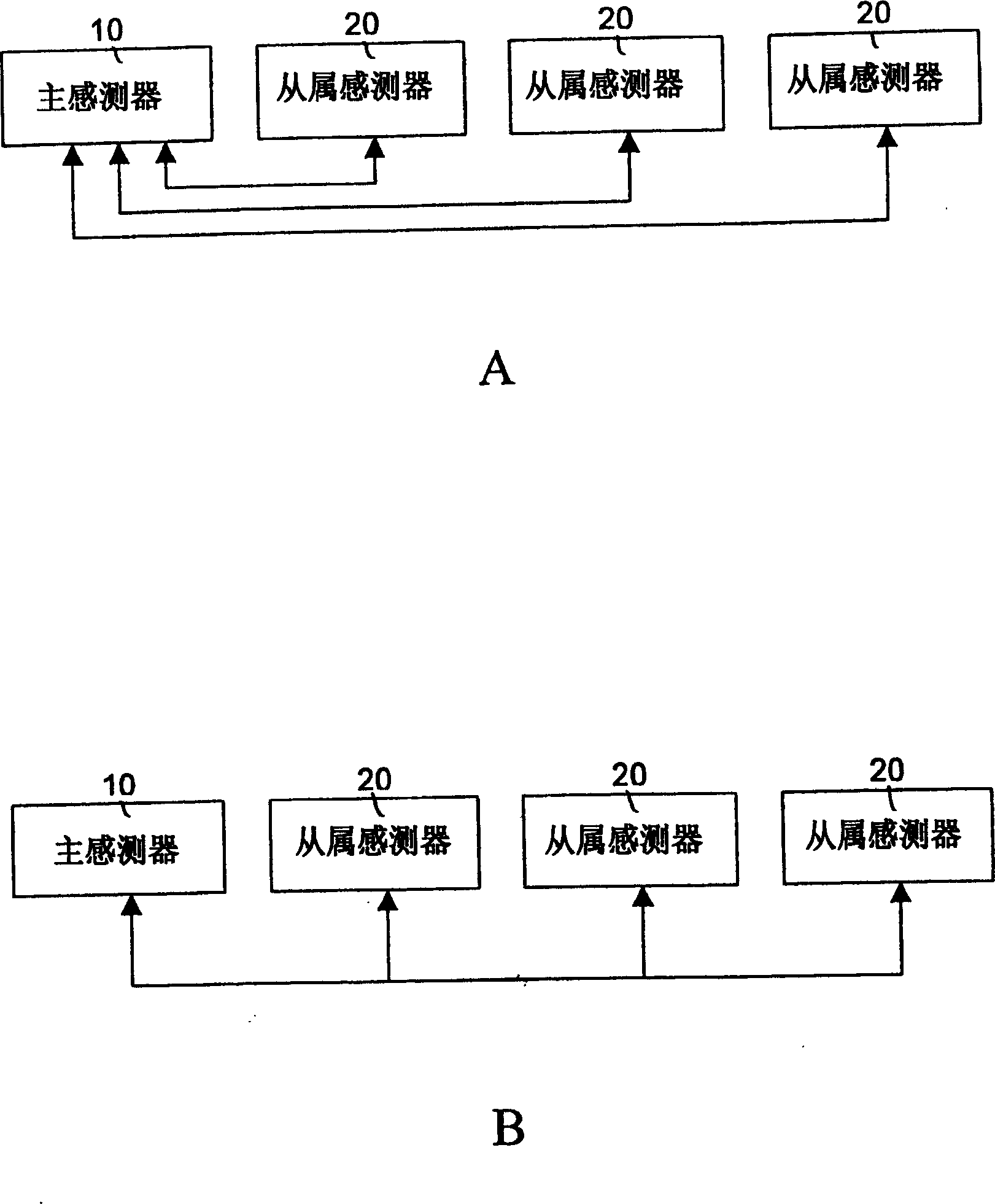
[0041] like figure 1 As shown, the system block diagram of the present invention is disclosed, which is composed of a master sensor 10 and a plurality of slave sensors 20; wherein: each slave sensor 20 can communicate with the master sensor 10 through an independent circuit. connected and communicated, but can also be connected and communicated through a single communication line; no matter what the connection method is, the master sensor 10 is polling with each slave sensor 20, each slave sensor 20 also sends its detection data to the main sensor 10 only when receiving the polling command from the main sensor 10 .

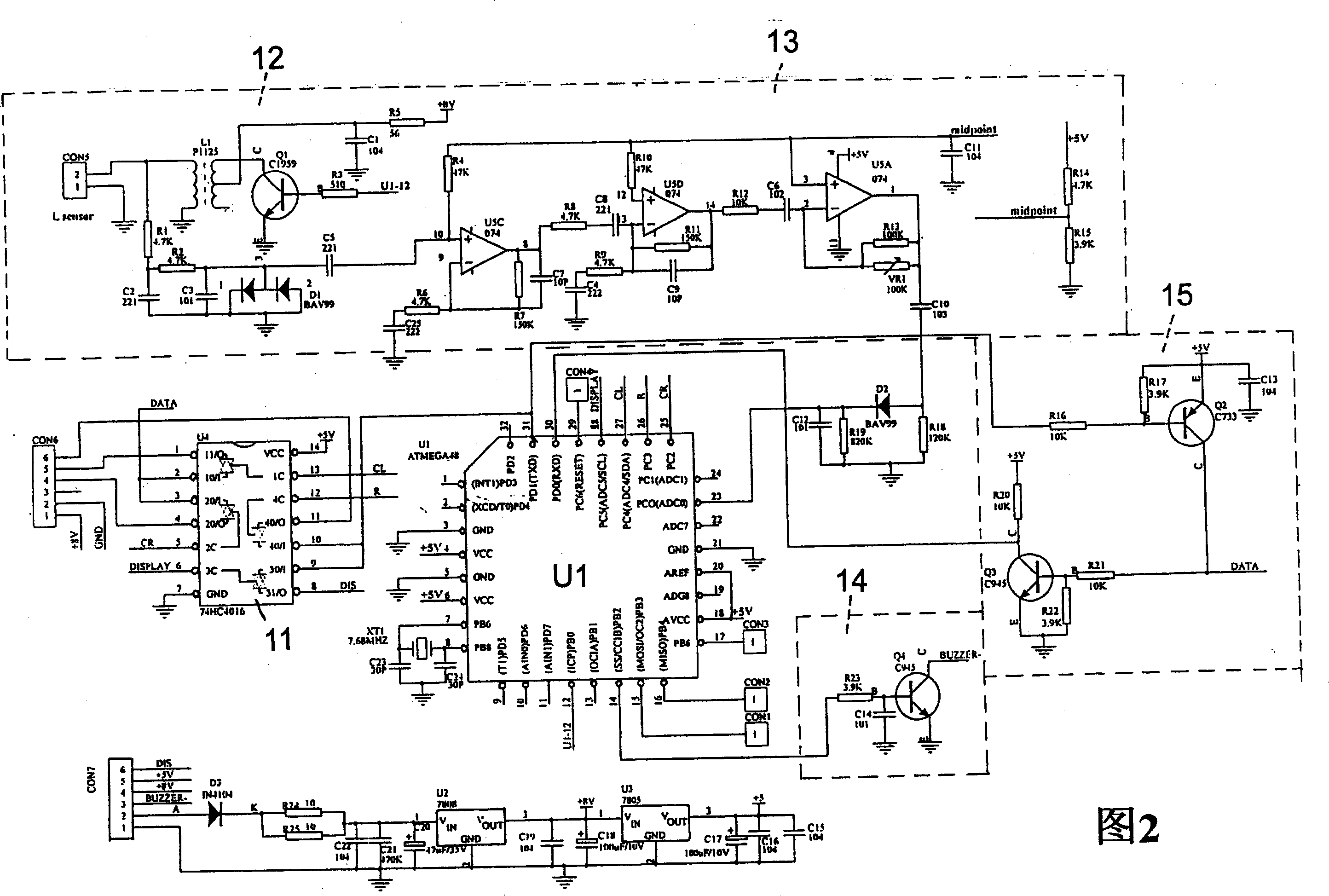
[0042] As for the detailed circuit structure of a feasible embodiment of the main sensor 10 as shown in Figure 2, it includes:

[0043] A microprocessor U1, in this embodiment, is made of ATMEGA8 chip produced by ATMEL company, it is responsible for generating 40KHz square wave and detecting the reflection signal from the obstacle, and through a gating circuit 1...


PUM


Abstract

The present invention refers to reversal radar set without control box. It contains at least one master sensor and one or more than one slave sensor; wherein said master sensor including through microprocessor, one gate circuit and one communication circuit and slave sensor for controlling each slave sensor, and collecting each slave sensor detecting result, master sensor also executing obstruction detection, its microprocessor according to itself and slave sensor detected result determining whether actuating alarm circuit, to alarm driver, without using independent control box.

Description

technical field [0001] The present invention relates to a reversing radar device without a control box, in particular to a reversing radar composed of master / slave sensors; The function of slave sensors to work and collect their detection results. Background technique [0002] Due to the development of electronic technology, the general public can enjoy the convenience and assistance brought by the development of technology. For example, reversing radar is a very specific example. The car owner installs the reversing radar on his car. When reversing or parking on the roadside, the obstacle detection function of the reversing radar can be used to assist him to complete the reversing or parking smoothly. The sensitivity of the reversing sensor and the installation setting and sensing There is a direct relationship between the number of devices. [0003] like Figure 4 As shown, a control box 80 is generally used to connect several ultrasonic sensors 81 to 84 in a parking ra...

Claims


Application Information

Patent Timeline
Patent Type & Authority Applications(China)
IPC IPC(8): G01S15/93G01S7/52
Inventor 李世雄
Owner COLIGEN CHINA
Why Eureka
Try Eureka