
Electronic equipment, and battery pack and load apparatus used in the same

一种电子设备、负载装置的技术,应用在电池电路装置、电路装置、电流供给装置等方向,达到提高能量利用效率、减少电功率损耗的效果

Inactive Publication Date: 2007-01-10
PANASONIC CORP
View PDF2 Cites 7 Cited by
  • Summary
  • Abstract
  • Description
  • Claims
  • Application Information

AI Technical Summary

Problems solved by technology

As a result, after boosting the output voltage of the fuel cell 101 to the output voltage of the secondary battery 102, the power supply of the functional circuit 303 that steps down the output voltage of the secondary battery 102 to be lower than the output voltage of the fuel cell 101 is performed. voltage, or on the contrary, after stepping down the output voltage of the fuel cell 101 to the output voltage of the secondary battery 102, the functional circuit 303 that boosts the output voltage of the secondary battery 102 to be higher than the output voltage of the fuel cell 101 is performed power supply voltage, so power conversion loss occurs in terms of energy utilization efficiency, which is an undesirable situation

Method used


Image

  • Electronic equipment, and battery pack and load apparatus used in the same
  • Electronic equipment, and battery pack and load apparatus used in the same
  • Electronic equipment, and battery pack and load apparatus used in the same

Examples


no. 1 example

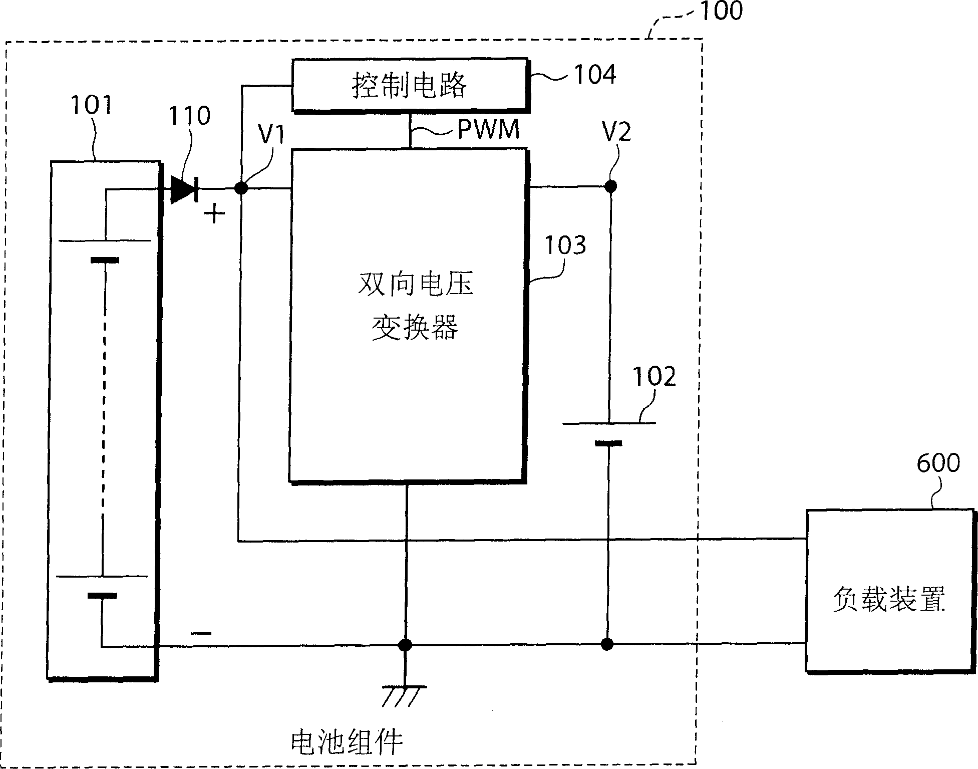
[0036] First, an electronic device according to a first embodiment of the present invention will be described. figure 1 is a block diagram of the electronic device according to the first embodiment of the present invention.

[0037] figure 1 The illustrated electronic equipment includes a battery assembly 100 including a fuel cell 101 , a secondary battery 102 , a bidirectional voltage converter 103 , a control circuit 104 , and a rectifying element 110 , and a load device 600 . The fuel cell 101 is an active type DMFC (Direct Methanol Fuel Cell) composed of six battery cells connected in series, and the secondary battery is composed of two lithium-ion batteries connected in series.

[0038] In addition, the fuel cell and the secondary battery are not limited to the above-mentioned examples, and passive DMFC, DDFC (Direct DME Fuel Cell), RMFC (Reformed Methanol Fuel Cell), etc. can also be used as the fuel cell. , and nickel metal hydride storage batteries can also be used...

no. 2 example

[0060] An electronic device according to a second embodiment of the present invention will be described below.

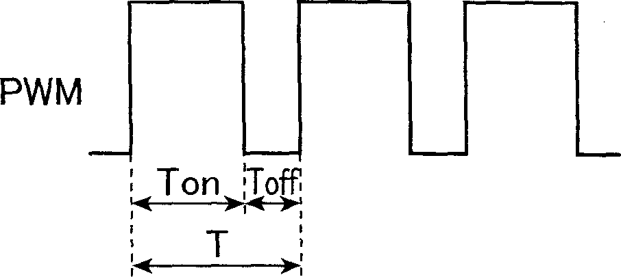
[0061] Figure 5 A circuit diagram showing the configuration of the step-down bidirectional voltage converter used in the electronic equipment according to the second embodiment of the present invention. In the electronic equipment of this embodiment, the output voltage of the fuel cell is set to be higher than the output voltage of the secondary battery, and the step-down bidirectional voltage converter is used to adjust the operating factor of the PWM signal input to the bidirectional voltage converter, so that the fuel cell The output voltage is 10V. Therefore, this embodiment differs from the first embodiment in that the figure 2 The boost bidirectional voltage converter 103 shown is changed to Figure 5 The step-down bidirectional voltage converter 103a shown, the rest are the same as figure 1 electronics shown, so use figure 1 Instead of an overall con...

no. 3 example

[0074] An electronic device according to a third embodiment of the present invention will be described below.

[0075] Figure 6 It is a block diagram showing the configuration of an electronic device according to a third embodiment of the present invention.

[0076] Figure 6 The illustrated electronic equipment includes a battery assembly 100 and a load device 200, the battery assembly 100 includes a fuel cell 101, a secondary battery 102, a bidirectional voltage converter 103, a control circuit 104, a rectifying element 110, a + terminal 106 of the secondary battery 102, The + terminal 107 of the fuel cell 101 and the common ground 108 of the secondary battery 102 and the fuel cell 101 .

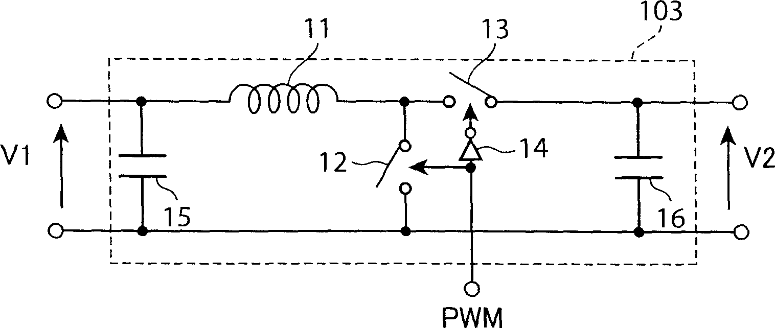
[0077] The bidirectional voltage converter 103 is the same as the first embodiment, consisting of figure 2 The shown boost bidirectional voltage converter 103 is constituted to boost the output voltage 2.4V of the fuel cell 101 to the output voltage 6-8.4V of the secondary battery 102...


PUM


Abstract

The bidirectional voltage converter is connected between the fuel cell and the secondary battery, and the load device is connected in parallel with the fuel cell. In addition, in the case of a plurality of voltage converters, if the respective output voltages are closer to the output voltage of the secondary battery than the output voltage of the fuel cell, they are divided into the first voltage converter group and compared with the output voltage of the secondary battery If the output voltage of the fuel cell is closer to the output voltage of the fuel cell, it is divided into the second voltage converter group, the first voltage converter group is connected in parallel with the secondary battery, and the second voltage converter group is connected in parallel with the fuel cell. Battery.

Description

technical field [0001] The present invention relates to an electronic device including a fuel cell, a battery pack and a load device used in the electronic device, and more specifically, relates to a circuit configuration of a suitable power supply unit thereof. Background technique [0002] Conventional power supplies for electronic devices such as notebook computers and mobile phones have a plurality of voltage converters, and the voltage converter for stepping down the voltage of the secondary battery and the voltage converter for boosting the voltage of the secondary battery output a large number of voltage converters. a voltage. As the input power source of the above-mentioned multiple voltage converters, a common method is to connect it to a secondary battery. [0003] Figure 10 It is a block diagram of commercially available electronic equipment such as notebook PCs. The battery assembly 400 does not include a fuel cell, but only consist...

Claims


Application Information

Patent Timeline
Patent Type & Authority Applications(China)
IPC IPC(8): H02J7/00H02J7/34H01M8/00G05F5/00G06F1/32H04M1/73
CPCH01M16/006Y10T307/511Y10T307/625Y10T307/675H02J7/34Y02E60/10Y02E60/50H01M8/04H02J7/00
Inventor 高田雅弘市濑俊彦嶋本健
Owner PANASONIC CORP
Features
  • Generate Ideas
  • Intellectual Property
  • Life Sciences
  • Materials
  • Tech Scout
  • Unparalleled Data Quality
  • Higher Quality Content
  • 60% Fewer Hallucinations
Learn More