Radiating module and its housing

A heat dissipation module and shell technology, applied in cooling/ventilation/heating transformation, instrument cooling, instrument, etc., can solve problems such as dead angle, dust accumulation, material limitation, etc., to save production and processing costs, selectivity more Flexible, highly selective effect

Inactive Publication Date: 2010-09-22
DELTA ELECTRONICS INC
View PDF0 Cites 0 Cited by
  • Summary
  • Abstract
  • Description
  • Claims
  • Application Information

AI Technical Summary

Problems solved by technology

Furthermore, in order to cooperate with the welding and electroplating process, the material of the iron shell cover 111 and the inlet ring 12 needs to be selected from an appropriate sheet metal material, such as a cold-rolled plate (Steel Plate Cold-rolled Commercial, SPCC), etc., so that the iron shell The materials that can be used for the cover 111 and the inlet ring 12 are limited
[0006] In addition, since the caliber of the inlet ring 12 shrinks in, a dead angle is formed in the space where the inlet ring 12 and the iron shell cover 111 are connected by welding, resulting in dust accumulation.
[0007] Based on the above, the inventors of this case are eager to think of a kind of "welding joint" that can solve the problems of unsightly alignment and welding points caused by welding the entrance ring and the iron shell cover, as well as the easy accumulation of dust between the entrance ring and the iron shell cover. Cooling module and its housing"

Method used


Image

  • Radiating module and its housing
  • Radiating module and its housing
  • Radiating module and its housing

Examples


Embodiment Construction

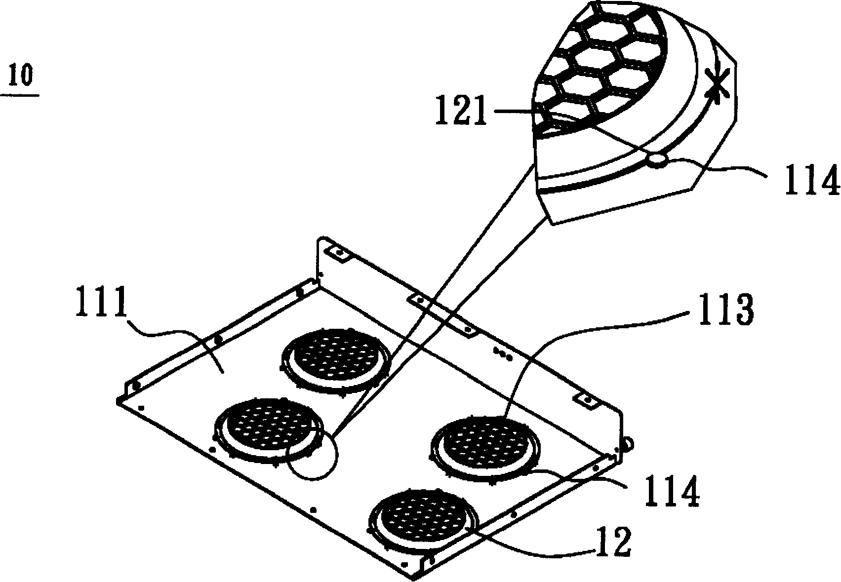
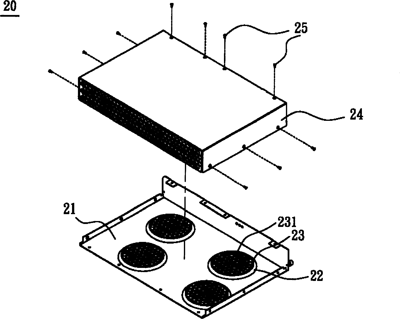
[0032] The heat dissipation module and its housing according to preferred embodiments of the present invention will be described below with reference to related drawings. First, please also refer to image 3 , Figure 4 and Figure 5 , to illustrate the housing of the heat dissipation module in the preferred embodiment of the present invention. image 3 It is a schematic diagram of a housing of a heat dissipation module in a preferred embodiment of the present invention, such as image 3 As shown, a housing 20 of a cooling module includes a first housing body 21 and a second housing body 24 . Figure 4 is a schematic diagram of the first shell body in a preferred embodiment of the present invention, and Figure 5 for along Figure 4 The schematic diagram of the cross-section of the guide part and the through-hole area made by the straight line C-C' in the middle. Note that, Figure 4 The first shell body 21 shown in, is connected with image 3 The direction in which th...


PUM


Abstract

The heat elimination module includes a shell part and at least a fan. The shell part includes a first shell body. The first shell body includes at least a diversion part, and at least a through-hole section. The diversion part and these through holes are integrated formed. The fan is setup inside shell body. Each fan is setup for each diversion part relatively. Each diversion part possesses firstend and second end relatively. The said first end is connected to the first shell body. The second end is setup around through-hole section. There are multiple through-holes in each through-hole section.

Description

technical field [0001] The invention relates to a heat dissipation module, in particular to a heat dissipation module with an improved casing. Background technique [0002] In order to avoid being polluted by dust in the atmosphere, general electronic products usually place electronic components in relatively closed casings. However, since the electronic components will generate high temperature during operation, if they are kept in high temperature state, it will easily lead to the loss of the components and shorten their lifespan. Therefore, in order to prevent electronic components from malfunctioning, a heat dissipation module is generally arranged next to the electronic components so as to quickly dissipate the heat generated by the internal operation of the electronic components to the outside. [0003] Such as figure 1 As shown, it is a schematic diagram of a known heat dissipation module 10 , and the heat dissipation module 10 includes a casing 11 , an inlet ring (...

Claims


Application Information

Patent Timeline
Patent Type & Authority Patents(China)
IPC IPC(8): G12B15/00H05K7/20
Inventor 林嘉庆陶鹏举庄德财黄文喜
Owner DELTA ELECTRONICS INC
Why Eureka
Try Eureka