
Temperature self-regulating soldering iron with removable tip

A cutting-edge, soldering iron technology, used in soldering irons, manufacturing tools, metal processing equipment, etc., can solve problems such as tip wear, and achieve the effects of easy disassembly, good heat transfer, and consistent welding performance

Active Publication Date: 2007-01-10
OK INT
View PDF4 Cites 5 Cited by
  • Summary
  • Abstract
  • Description
  • Claims
  • Application Information

AI Technical Summary

Problems solved by technology

[0009] Another problem with soldering irons in general is that their tips wear down over time, requiring replacement

Method used


Image

  • Temperature self-regulating soldering iron with removable tip
  • Temperature self-regulating soldering iron with removable tip

Examples


Embodiment Construction

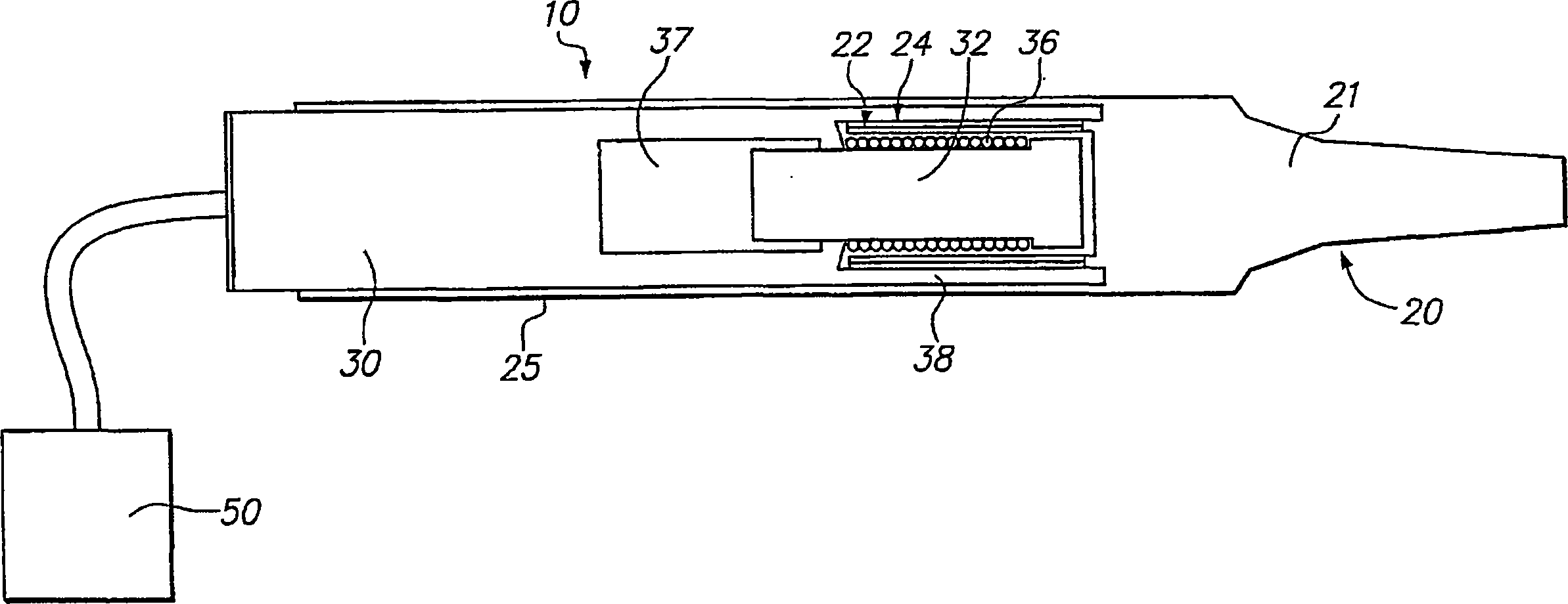
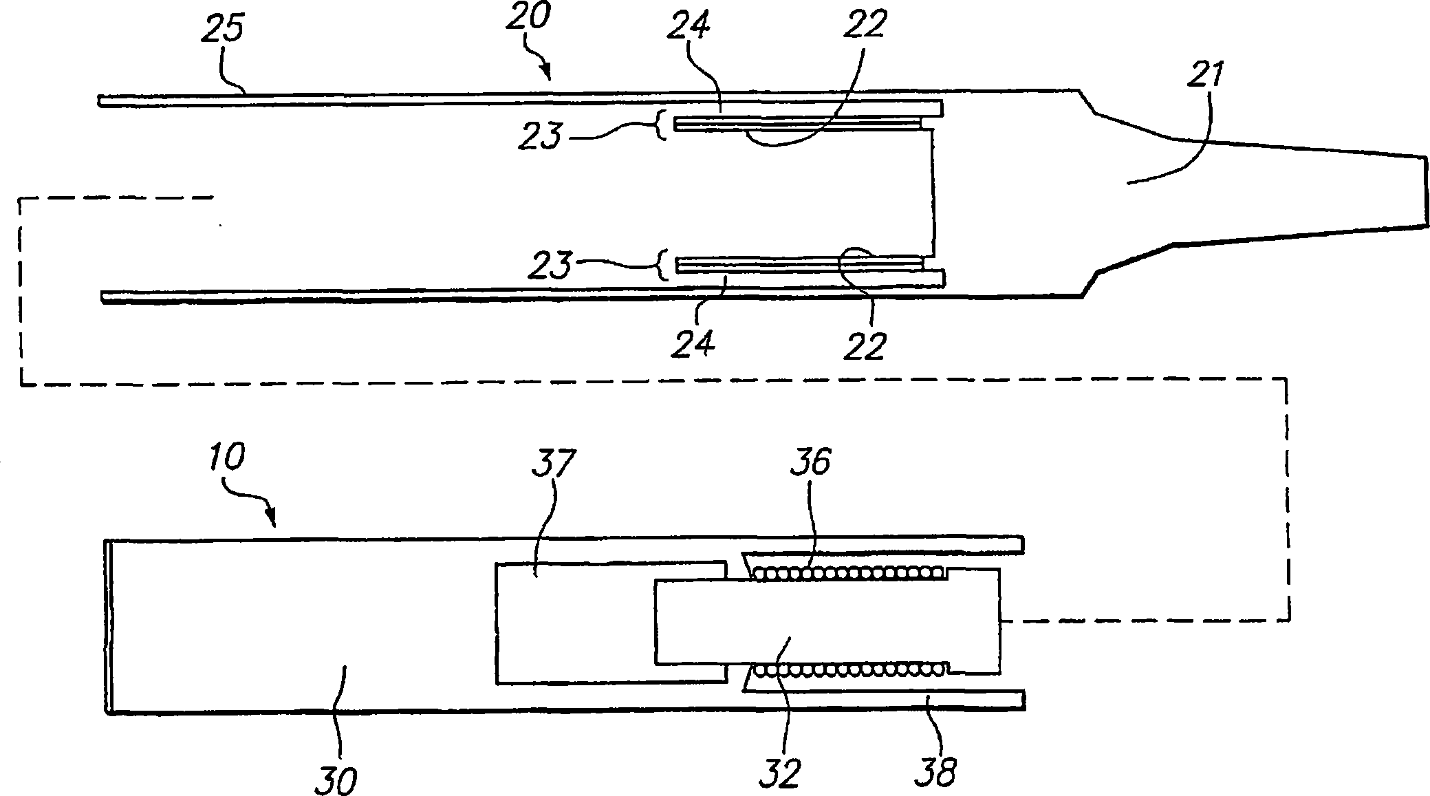
[0031] figure 1 It is an assembly drawing of a soldering iron shaft with a detachable tip located on it. figure 2 It is an exploded view with the tip removed.

[0032] The present invention provides a soldering iron 10 with a detachable tip 20. The soldering iron 10 includes a shaft 30 having a ferrite bobbin 32 mounted thereon. The magnetic coil 36 is wound around the ferrite bobbin 32.

[0033]A detachable tip 20 is also provided. The detachable tip 20 includes a main body 21 having a heating element 23 extending therefrom. Most preferably, the heating element 23 includes a cylindrical inner alloy heating layer 22 surrounding the cylindrical outer layer 24. When the detachable tip 20 is located on the soldering iron 10, the size of the heating element 23 is designed such that the inner alloy heating element 22 is accommodated around the magnetic coil 36.

[0034] By improving the magnetic circuit formed between the heating layer 22 and the magnetic coil 36, the ferrite bobbin ...


PUM

PropertyMeasurementUnit
diameteraaaaaaaaaa

Abstract

A soldering iron (10) with a detachable tip (20), comprising: a soldering iron (10) comprising: a shaft (30); a ferrite bobbin (32) positioned on the shaft (30); wound on a magnetic coil (36) around a ferrite bobbin (32); and a removable tip (20) with a heating element (23) located thereon, wherein the heating element (23) is sized to be When the tip (20) is on the soldering iron (10), it fits around the magnetic coil (36).

Description

Technical field [0001] The invention relates to a soldering iron. Background technique [0002] The Delaware (State) Investment Company Metcal has an advanced self-adjusting temperature soldering iron system in which alloy heating elements are located in magnetic solenoid coils. This structure is called "solenoid coupling". The advantage of this design is that the magnetic efficiency is very high. Examples of such solenoid coupling systems can be found in U.S. Patent Nos. 4,745,264 and 4,839,501, both of which were designed by Delaware (State) Investment Corporation. [0003] Unfortunately, although the magnetic efficiency of solenoid-coupled designs is very high, they do not achieve the desired thermal efficiency. This is because of the relatively small size (and small cross-section) of the heating element contained in the surrounding magnetic solenoid coil. Due to their small cross-section through which heat is conducted axially, such small-sized heating elements have a relativ...

Claims


Application Information

Patent Timeline
Patent Type & Authority Applications(China)
IPC IPC(8): B23K3/03B23K3/047
CPCB23K3/0478
Inventor M·考威尔K·李M·卡尔洛马格诺
Owner OK INT
Learn More