
Cylinder of closed compressor

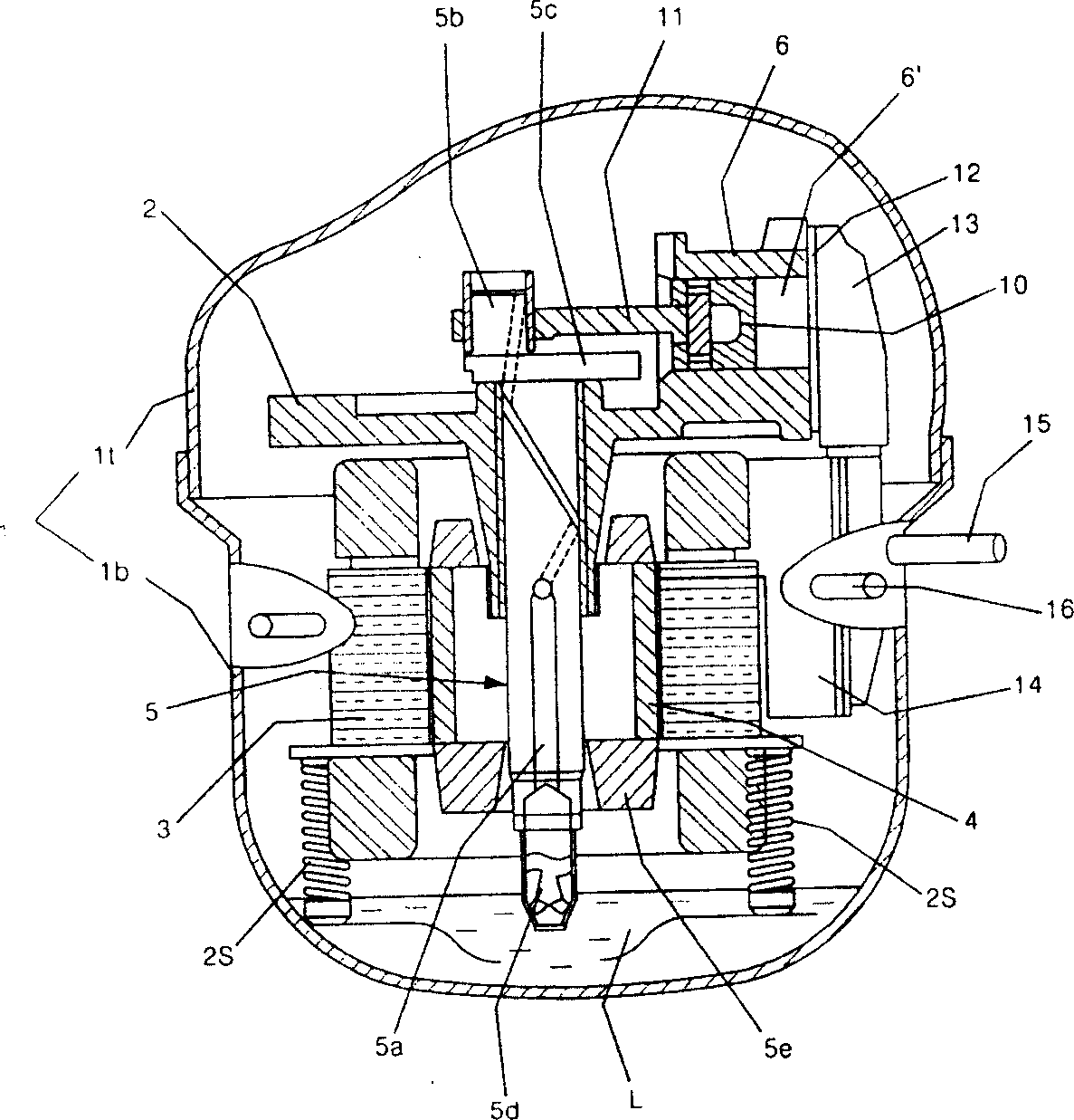
A compressor and sealing technology, which is applied in the direction of mechanical equipment, machines/engines, liquid displacement machines, etc., can solve problems such as increased friction, inconvenience, wear of the compression chamber 6' and piston 10, and achieve improved friction , wear reduction effect

Inactive Publication Date: 2007-01-17
LG ELECTRONICS (TIANJIN) APPLIANCES CO LTD
View PDF0 Cites 3 Cited by
  • Summary
  • Abstract
  • Description
  • Claims
  • Application Information

AI Technical Summary

Problems solved by technology

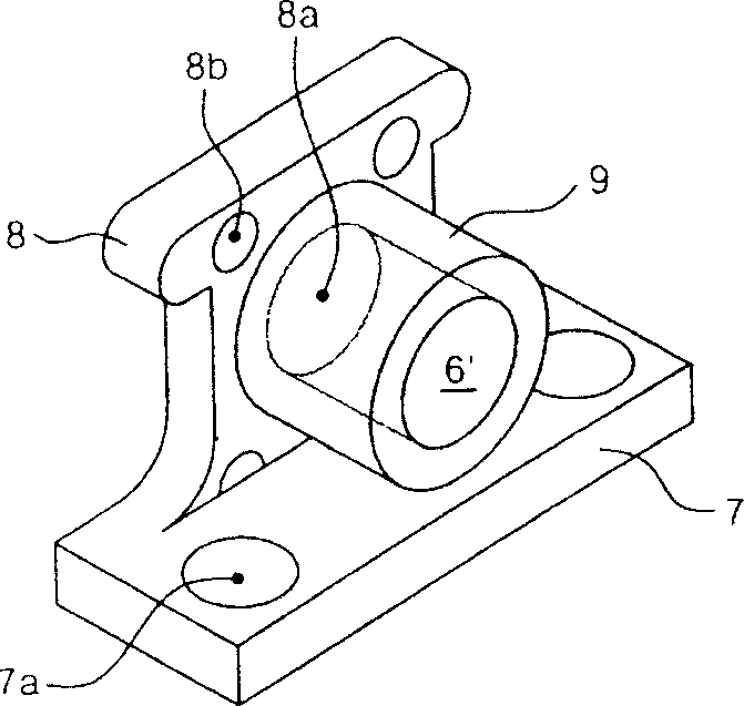
[0016] According to the above, the existing cylinder device has the problem of increased friction due to the large relative friction area between the above-mentioned compression chamber 6' and the piston 10.
[0017] In addition, the distance between the above-mentioned compression chamber 6' and the piston 10 is quite narrow, so only a small amount of the oil scattered from the crankshaft 5 flows between the above-mentioned compression chamber 6' and the piston 10, so that the pressure between the compression chamber 6' and the piston 10 occurs. 10 wear
[0018] This shows that the cylinder of the above-mentioned existing hermetic compressor clearly still has inconvenience and defects in structure and use, and needs to be further improved urgently.
In order to solve the problems existing in the air cylinders of hermetic compressors, relevant manufacturers have tried their best to find a solution, but no suitable design has been developed for a long time, and there is no suitable structure for general products to solve the above problems , this is obviously a problem that relevant industry players are eager to solve

Method used


Image

  • Cylinder of closed compressor
  • Cylinder of closed compressor
  • Cylinder of closed compressor

Examples


Embodiment Construction

[0050] In order to further explain the technical means and effects that the present invention takes to achieve the intended purpose of the invention, below in conjunction with the accompanying drawings and preferred embodiments, the specific implementation, structure, characteristics and details of the cylinder of the hermetic compressor proposed according to the present invention will be described below. Its effect is described in detail below.

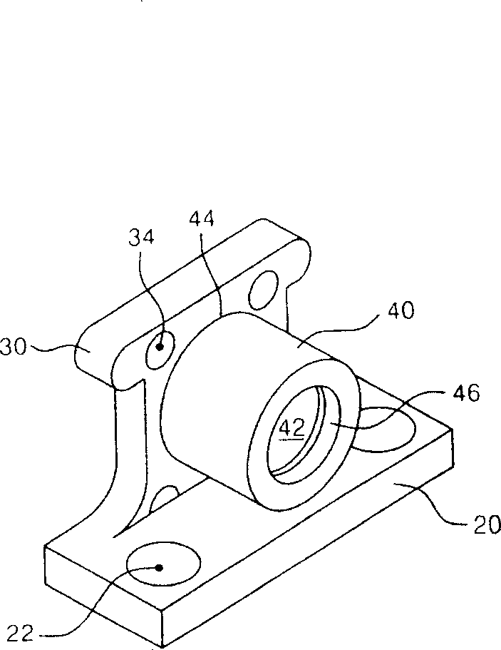
[0051] see Figure 3 ~ Figure 5 shown, where image 3 It is a schematic diagram of a suitable embodiment of the cylinder device according to the present invention; Figure 4 It is a cross-sectional view of an embodiment of the present invention; Figure 5 It is a longitudinal sectional view showing the relationship between the embodiment of the present invention and the piston.

[0052] As shown in the figure, the above-mentioned cylinder device includes an integrally formed cylinder base 20 ; a cylinder front 30 ; and a cylinder ...


PUM


Abstract

This invention is a kind of air cylinder of hermetic compressor. It includes air cylinder base; air cylinder body and breaking section. The air cylinder base is to connect to the frame; the said air cylinder body is above the said air cylinder base and has compressing chamber cutting through the interior. The valve components, which control working fluid to get in and out, are mounted at one end; the said breaking section is at the lowest point side of the said compressing chamber. It can reduce friction of pistons, which move along the inner face of the said compressing chamber.

Description

technical field [0001] The present invention relates to a hermetic compressor, more specifically, a cylinder of the hermetic compressor provided with a compression chamber for compressing a working fluid inside and installed on a frame. Background technique [0002] Here, the cylinder device according to the present invention is generally composed of a cylinder base; a cylinder body; and a gap part, usually made by sintering. However, in this detailed description, a cylinder device composed of a cylinder base; a cylinder front; a cylinder block; This is because the present invention is applicable to general cylinder devices, and the main structural feature of the present invention lies in the shape and arrangement of the gaps, so there is no problem with the difference in other components other than the gaps. [0003] Generally speaking, hermetic compressors can be divided into scotch yoke and connecting rod type according to the method of converting the rotation of the cra...

Claims


Application Information

Patent Timeline
IPC IPC(8): F04B39/12
Inventor 李虎成曹必镐
Owner LG ELECTRONICS (TIANJIN) APPLIANCES CO LTD
Learn More