Fuel cell with catalytic heater

A fuel cell and fuel cell stack technology, which is applied in the directions of fuel cells, fuel cell additives, electrochemical generators, etc., can solve the problems of reducing the conductivity of electrolyte composites, achieve fast and uniform operating temperature, and accelerate heating. Effect

Inactive Publication Date: 2007-01-17
ROBERT BOSCH GMBH
View PDF0 Cites 5 Cited by
  • Summary
  • Abstract
  • Description
  • Claims
  • Application Information

AI Technical Summary

Problems solved by technology

Contact of the membrane electrolyte with liquid water is detrimental because the water may wash away the electrolyte components (such as phosphoric acid) complexed in a polymer array, which reduces the conductivity of the electrolyte complex

Method used


Image

  • Fuel cell with catalytic heater
  • Fuel cell with catalytic heater
  • Fuel cell with catalytic heater

Examples


Embodiment Construction

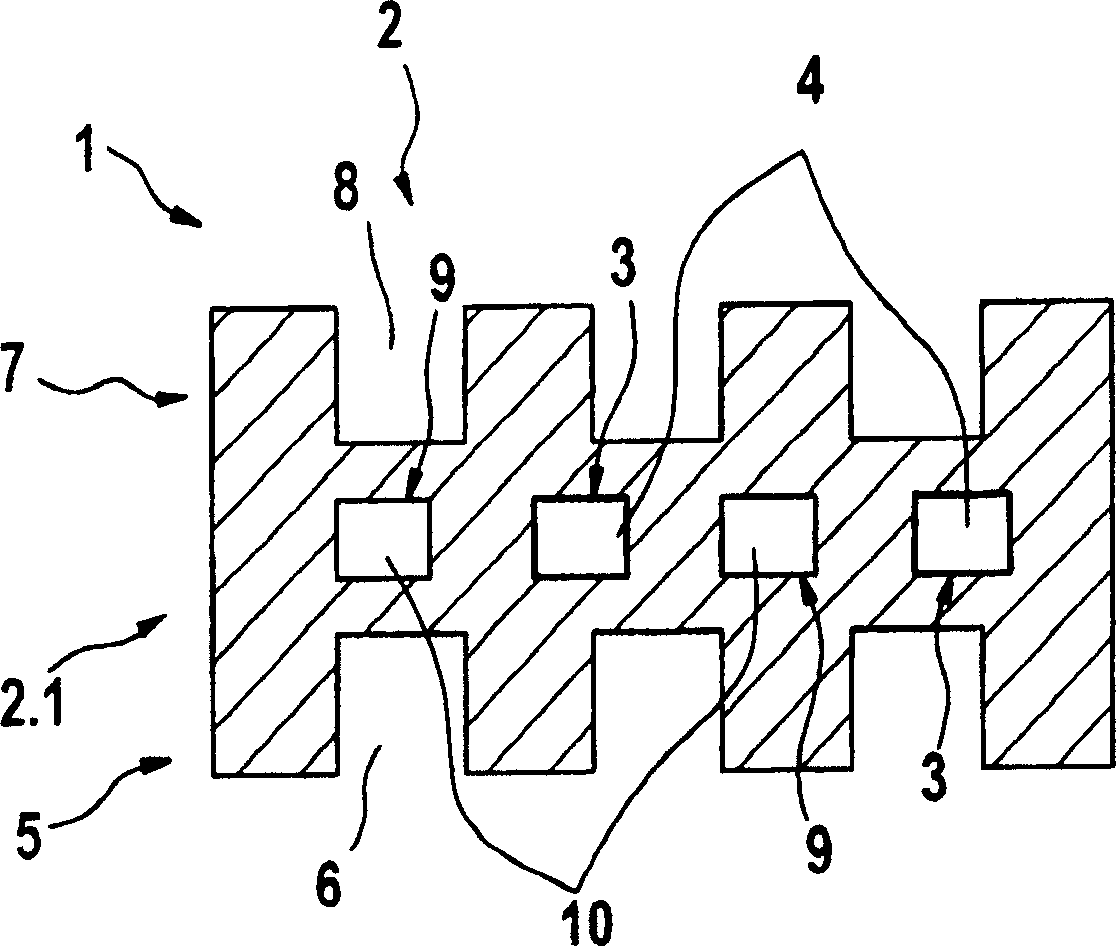
[0022] figure 1 A cross-sectional view of a bipolar plate 2 of a fuel cell 1 with heating channels 4 of a heater 3 based on the heat of catalytic reactions is shown. This configuration of the heating channel 4 is a preferred embodiment, but can of course differ from this embodiment. In particular, additional heating channels 4 can also be provided, for example on end plates (not shown).

[0023] The bipolar plate 2 shown here is therefore divided into, in addition to the main body 2.1 with the heating channels 4 , a region 5 adjacent to the main body, pointing downwards in the drawing, and another region opposite this in the drawing. The upper part 7 pointing upwards. The lower part 5 has fuel channels 6 formed therein as fuel-carrying component 5 . The upper part 7 has oxidant channels 8 formed therein as oxidant-carrying component 7 .

[0024] The exemplary embodiment of a bipolar plate 2 of a fuel cell 1 shown here is also equipped with cooling 9 , which is realized by ...


PUM


Abstract

The invention relates to a type of fuel cell, especially a polymer-electrolyte-fuel cell. According to this invention, the fuel cell is provided with a heater (3) based on catalytic reaction heat for quickly and uniformly heating the fuel cell. This is carried out only in case of the temperature being obviously higher than the ambient temperature or it is helpful to the fuel cell allowing occurrence of electrochemical reation.

Description

technical field [0001] The invention relates to a fuel cell according to the preamble of claim 1 . Background technique [0002] The proper operation of a fuel cell is strongly dependent on its operating temperature. In particular, undesired operating conditions occur during start-up operation of a fuel cell. On the one hand, the efficiency is poor due to too low operating temperature and / or the electrical conversion rate is too low, and on the other hand fuel cells are known, in which the discharge of liquid water comes into contact with the electrolyte and can even cause damage. [0003] For example, for the operation of polymer-electrolyte fuel cells at operating temperatures above 120° C. membrane electrolytes can be used which have an ion-conducting mechanism which is not water-based. Contact of the membrane electrolyte with liquid water is detrimental because the water may wash away the electrolyte components (eg, phosphoric acid) complexed in a polymer matrix, which...

Claims


Application Information

Patent Timeline
Patent Type & Authority Applications(China)
IPC IPC(8): H01M8/04
CPCH01M8/04074Y02E60/50
Inventor G·阿伦德斯O·马奎德特
Owner ROBERT BOSCH GMBH
Why Eureka
Try Eureka