Small piezoelectric or electrostrictive linear motor

A linear motor and telescopic technology, applied in the field of China and Israel

Active Publication Date: 2007-01-17
PIEZOELECTRIC TECH
View PDF0 Cites 12 Cited by
  • Summary
  • Abstract
  • Description
  • Claims
  • Application Information

AI Technical Summary

Problems solved by technology

[0011] [11] Although the bending displacement of the piezoelectric substrate upon application of an electric field has been described, even if an electro

Method used


Image

  • Small piezoelectric or electrostrictive linear motor
  • Small piezoelectric or electrostrictive linear motor
  • Small piezoelectric or electrostrictive linear motor

Examples


Embodiment Construction

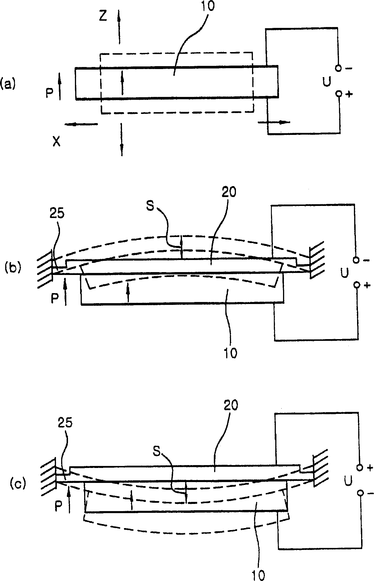
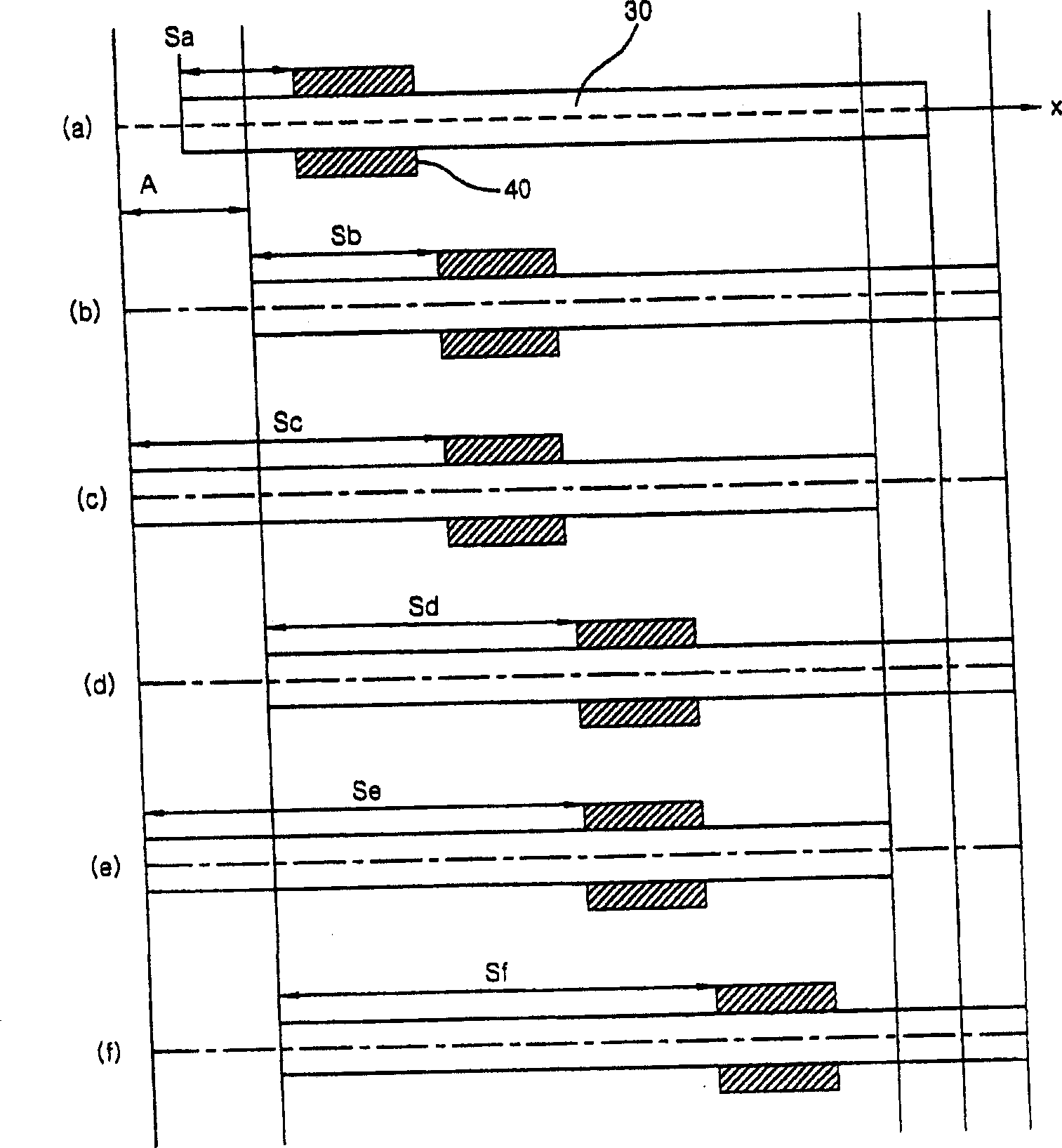
[0039] In order to achieve the above object, the present invention provides a basic structure including a piezoelectric or electrostrictive substrate 10 , a movable body 40 , a movable shaft 30 and an elastic body 20 . Also, in the present invention, various types of small piezoelectric / electrostrictive ultrasonic linear motors including linear motors having three structures that will be explained in the preferred embodiments are proposed based on the above basic configuration.

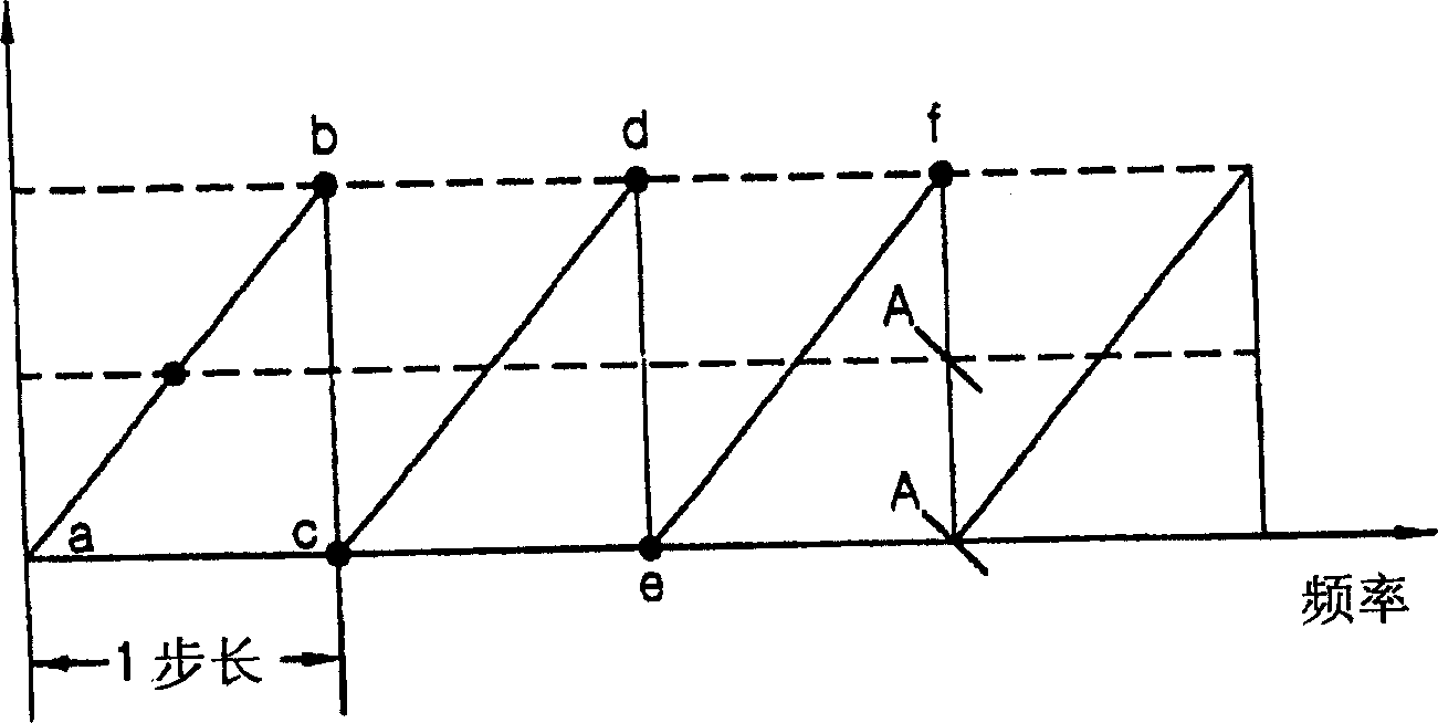
[0040] Figure 4 , Figure 5 and Figure 6 Three small piezoelectric / electrostrictive ultrasonic linear motors with the basic configuration described above are shown.

[0041] Figure 4 A first embodiment of the present invention including a piezoelectric or electrostrictive substrate 10 , an elastic body 20 and a movable body 40 is shown. The assembly of the piezoelectric or electrostrictive substrate 10 and the elastic body 20 forms a unimorph having a disk shape. The elastic body 20 is not lim...


PUM


Abstract

The present invention provides a small piezoelectric/electrostrictive ultrasonic linear motors which are installed in cell phones or PDAs, etc. to drive their camera lenses. In the present invention, a movable shaft (30) is coupled to a unimorph or bimorph, which is made by attaching a piezoelectric or electrostrictive substrate to an elastic body (20) (metal), so that a movable body (40) fitted over the movable shaft (30) is linearly moved along the movable shaft (30) by vibration of the piezoelectric or electrostrictive substrate, thus simplifying a manufacturing process, being easily practicable according to a basic principle, and having superior characteristics.

Description

technical field [0001] The present invention generally relates to a small piezoelectric / electrostrictive ultrasonic linear motor installed in a cellular phone or a PDA or the like to drive its camera lens, and more particularly to such a small piezoelectric / electrostrictive ultrasonic linear motor in which The movable shaft 30 is coupled to a unimorph or bimorph made by attaching a piezoelectric or electrostrictive substrate to an elastic body 20 (metal), so that The movable body 40 on the upper linearly moves along the movable shaft 30 by the vibration of the piezoelectric or electrostrictive substrate, thereby simplifying the manufacturing process, and being easy to practice according to the basic principle and having superior characteristics. Background technique [0002] A small stepper motor that can be installed in a cell phone or PDA etc. to drive its camera lens must be provided with reduced gears and cams to convert high speed rotation into linear motion. In additi...

Claims


Application Information

Patent Timeline
IPC IPC(8): H02N2/04
CPCH02N2/006H02N2/0065G02B7/02H02N2/04H10N30/88
Inventor 瓦西耶福·皮奥特金潽根尹锡民尹成日
Owner PIEZOELECTRIC TECH
Why Eureka
Try Eureka