Test table for life saving boat lowering device
A lifeboat and test bench technology, which is applied in the direction of measuring devices, machine/structural component testing, instruments, etc., can solve the problems of high work intensity, untrue test status, and poor safety assurance, and achieve low investment, time-saving testing, and Easy to use effects
- Summary
- Abstract
- Description
- Claims
- Application Information
AI Technical Summary
Problems solved by technology
Method used
Image

Examples
Embodiment Construction
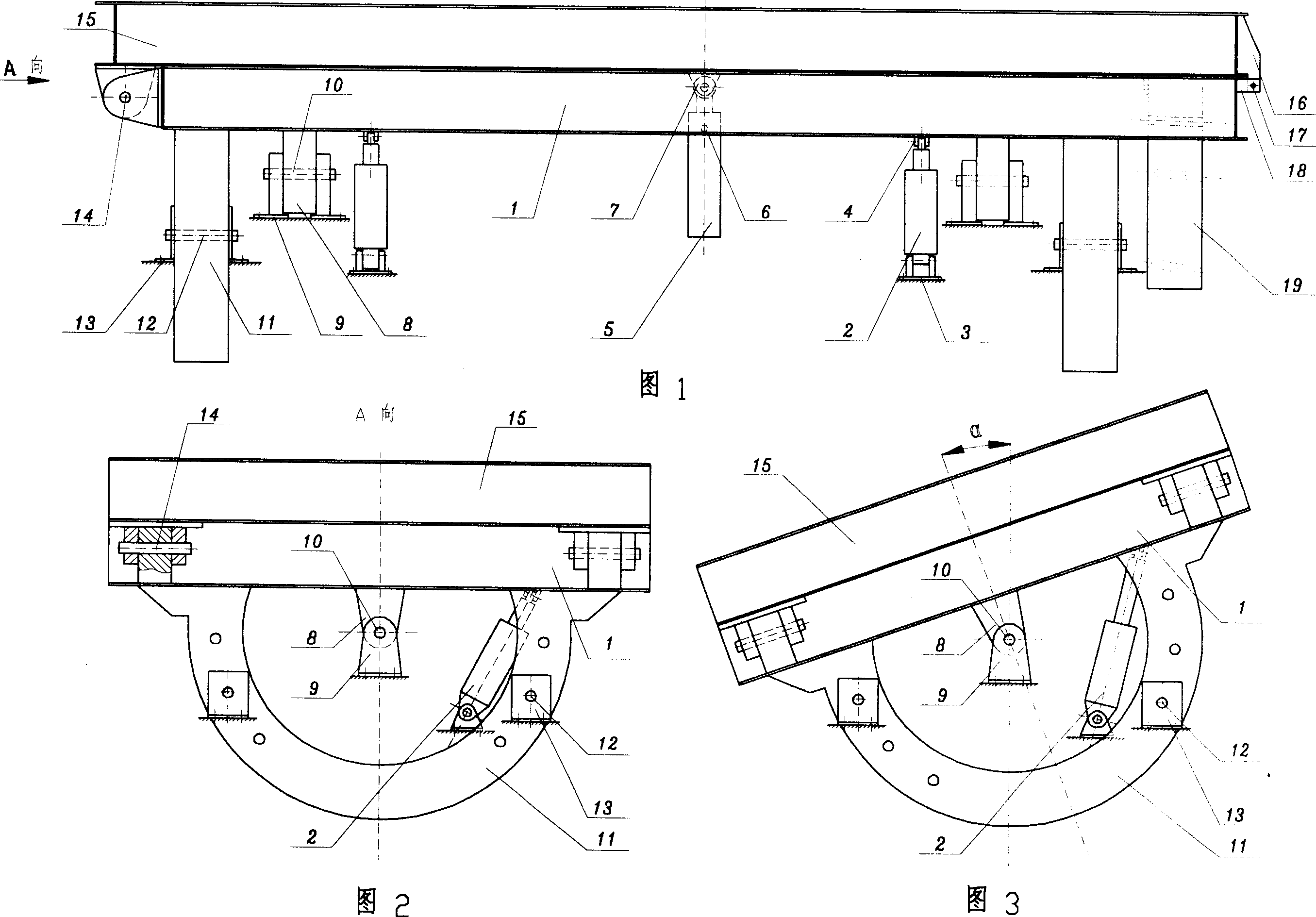
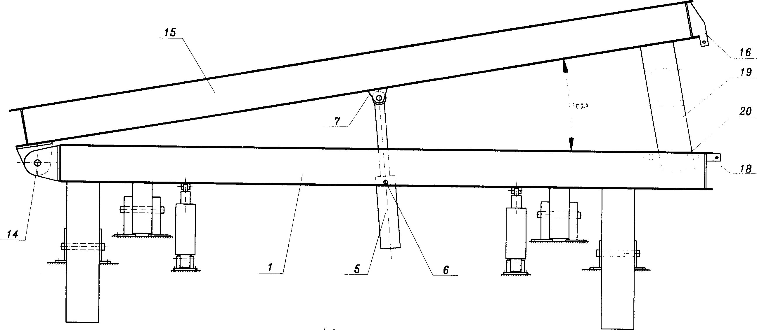
[0018] Description with reference to the accompanying drawings. In Fig. 1, the upper platform 15 and the lower platform 1 adopt a rectangular frame structure. The rear end of the upper platform 15 is connected to the rear end of the lower platform 1 through the trim shaft 14, and the trim oil cylinder 5 is respectively connected with the front swing shaft support 6 of the trim oil cylinder and the upper hinge seat 7 of the trim oil cylinder and is rotatable and telescopic. The front swing shaft support 6 of the oil cylinder is connected with the lower platform 1, the upper hinge seat 7 of the trim oil cylinder is welded on the upper platform 15, the trim oil cylinder 5 is a middle hinge type, the diameter of the piston rod is φ125 mm, the diameter of the piston is φ200 mm, and the stroke is 1300 mm . The upper end and the lower end of the heel cylinder 2 are respectively connected with the upper hinge seat 4 of the heel cylinder and the lower hinge seat 3 of the heel cylinder...
PUM
 Abstract
Description
Claims
Application Information