Electromagnetic compatible protector for display device and display device

A protective device, electromagnetic compatibility technology, applied in the identification device, electrical components, magnetic field/electric field shielding and other directions, can solve the problems of reducing electromagnetic interference, poor resistance to external electromagnetic interference, inconvenient production and application, etc., to enhance anti-static, Strong anti-static, wide temperature range effect

Active Publication Date: 2007-01-24
BEIJING VISIONOX TECH +1
View PDF0 Cites 13 Cited by
  • Summary
  • Abstract
  • Description
  • Claims
  • Application Information

AI Technical Summary

Problems solved by technology

At present, in the field of display, most display modules only realize the display function, and rarely consider circuit stability and electromagnetic protection, and their ability to resist external electromagnetic interference is relatively poor. In order to reduce electromagnetic interference, many products use single-chip Body connection, or the row drive control chip and the column drive control chip are connected to the screen body separately, but the above design still cannot reduce the electromagnetic interference well, so in order to make the product achieve better anti-interference ability, it is necessary to design the module of the product Improvement, which brings a lot of inconvenience to actual production and application

Method used


Image

  • Electromagnetic compatible protector for display device and display device
  • Electromagnetic compatible protector for display device and display device
  • Electromagnetic compatible protector for display device and display device

Examples


Embodiment 1

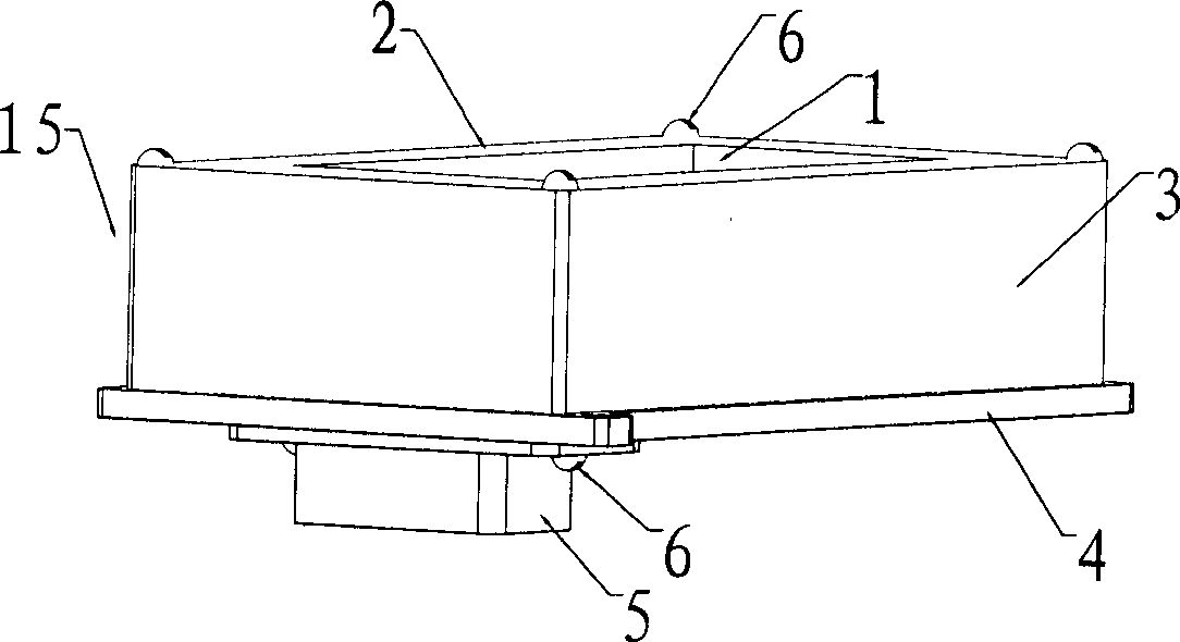
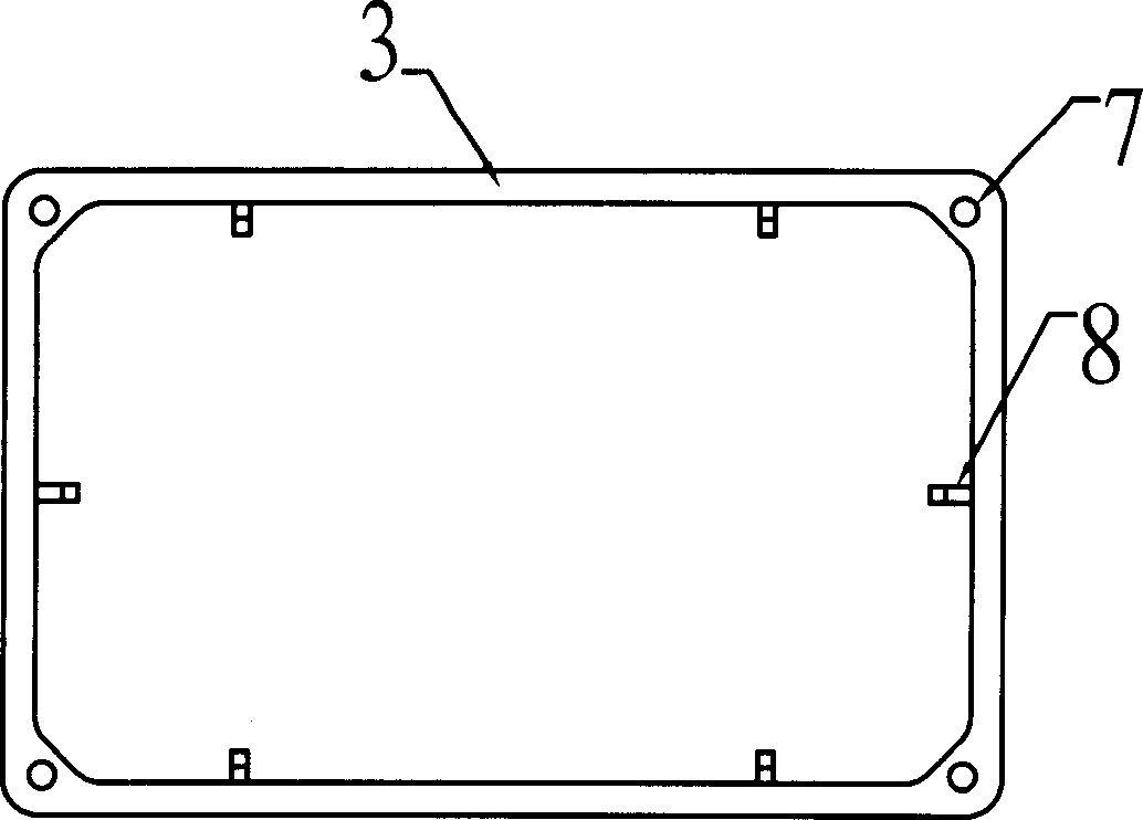
[0033] figure 1 It is a three-dimensional side view of an embodiment of the electromagnetic compatibility protection device of the present invention. In this embodiment, the electromagnetic compatibility protection device is a rectangle, and the panel 2 of the protection device is connected with the side walls 3 extending along the four sides of the panel to form a box-shaped opening The outer shell 15, the panel 2 is provided with a display area 1, the outer shell 15 and the back plate 4 are connected together by the screws 6 arranged at the four corners of the shell to form a closed structure, and the outer wall of the back plate 4 is provided with an electrical connector 5 . image 3 It is a view of the inner side wall of the shell of the electromagnetic compatibility protection device of the present invention. It can be seen from the figure that six ribs 8 are provided on the four side walls 3 inside the shell to connect the shell with the flat plate placed therein. The d...

Embodiment 2

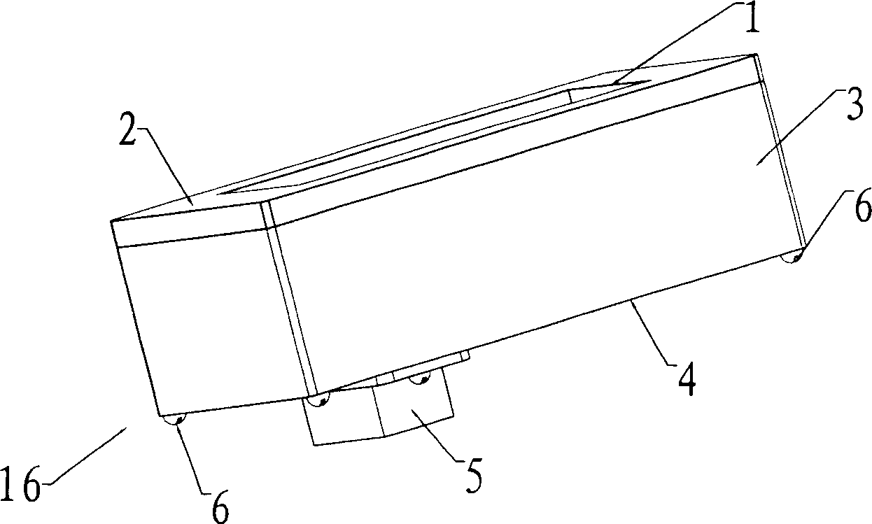
[0035] figure 2 It is a three-dimensional side view of another embodiment of the electromagnetic compatibility protection device of the present invention. In this embodiment, the electromagnetic compatibility protection device is a square, and the back plate 4 of the protection device is connected with the side walls 3 extending along the four sides of the back plate. The casing 16 with a box-shaped opening, the panel 2 is provided with a display area 1 , the casing and the panel 2 are connected together by screws 6 arranged at four corners of the casing, and the outer wall of the backplane 4 is provided with an electrical connector 5 . Also, four convex ribs are provided on the four side walls inside the casing to keep the casing in mechanical contact with and fix the flat-panel display placed therein and prevent the display from sliding. The display area and shell material of the electromagnetic compatibility protection device are all selected from polyvinyl chloride, and t...

Embodiment 3

[0037] Figure 4 is a cross-sectional view of an organic electroluminescent display device in the present invention. Figure 5 It is a structural schematic diagram of an organic electroluminescent display device in the prior art, Figure 6 It is a structural schematic diagram of the organic electroluminescence display device in the present invention. In the prior art, most of the displays are connected to the screen body by a single chip, and there are also row and column drive control chips connected to the screen body respectively, such as Figure 4 As shown, usually the display screen is connected to the drive control chip and then connected to the circuit board. There is a power supply unit on the circuit board, and the connection with the user control interface is realized through the signal line row of holes. The display module in the prior art only realizes the display function. There are few considerations for circuit stability and electromagnetic protection.

[003...


PUM


Abstract

This invention relates to an electromagnetic compatible protection device and a display, in which, the protection device is composed of a shell forming a closing structure, a display region is set on the shell, a conductive light transmission material covers on the inside wall of the display region and an electromagnetic wave shield material with conduction function covers the inside wall of the display apart from the display region and an electric connector is set on the shell, a TVS tube or a piezeoresistor is set on the CB apart from the protection device and the control chip is packaged by a ceramic shell.

Description

technical field [0001] The invention relates to electromagnetic interference suppression technology, in particular to the electromagnetic interference suppression technology in the display field and a display device with anti-electromagnetic interference capability. Background technique [0002] With the increase in the types and numbers of electronic equipment, the electromagnetic compatibility (abbreviated as EMC) of electronic equipment has attracted more and more attention. Electromagnetic compatibility means that electronic equipment and systems can still coordinate and The ability to work effectively. The purpose involved in electromagnetic compatibility is to enable electronic equipment to suppress various external interferences, work normally in a specific electromagnetic environment, and at the same time reduce its own electromagnetic interference to other electronic equipment. At present, in the field of display, most display modules only realize the display funct...

Claims


Application Information

Patent Timeline
IPC IPC(8): H05K9/00G09F9/00
Inventor 邱勇孙铁朋
Owner BEIJING VISIONOX TECH
Why Eureka
Try Eureka