Cooling system for the cooling of heat-producing devices in an aircraft

A cooling system and equipment technology, applied in lighting and heating equipment, aircraft kitchens, aircraft parts, etc., can solve the problem of inflexible space distribution, and achieve the effect of flexible layout, reliable cooling system, and increased reliability

Inactive Publication Date: 2007-01-24
AIRBUS OPERATIONS GMBH
View PDF1 Cites 22 Cited by
  • Summary
  • Abstract
  • Description
  • Claims
  • Application Information

AI Technical Summary

Problems solved by technology

However, the disadvantage of this prior art is that each cooling chamber requires a separate cold air chamber
This means that the spatial distribution within the aircraft becomes less flexible

Method used


Image

  • Cooling system for the cooling of heat-producing devices in an aircraft
  • Cooling system for the cooling of heat-producing devices in an aircraft

Examples


Embodiment Construction

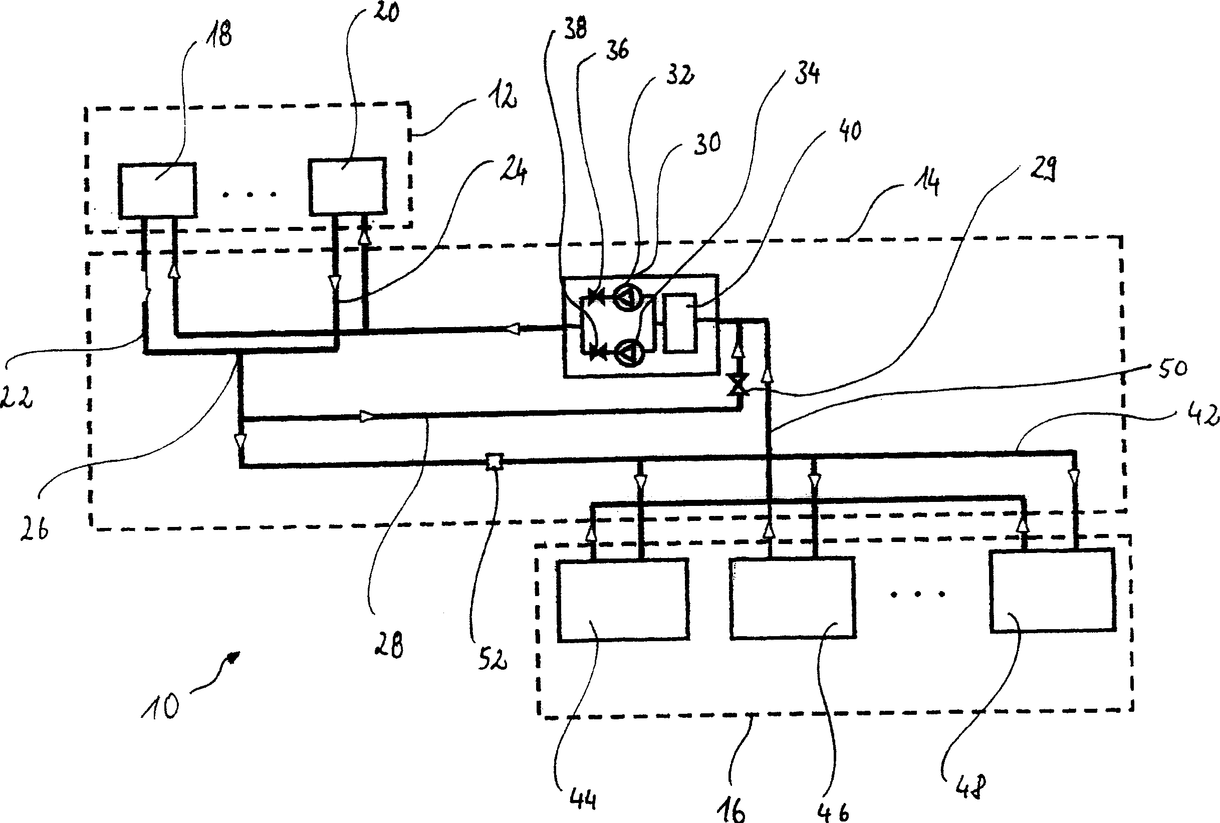
[0026] in the attached figure 1 , the cooling system according to the present invention is shown with reference numeral 10 . It includes refrigeration equipment 12 , a cold delivery system 14 , and an area 16 that consumes cold.

[0027] The refrigeration plant 12 has two coolers 18 and 20 in which the cold carrier medium is cooled by the cold evaporation process known in the field of thermodynamics and supplied to the cold transfer system 14 along two parallel lines 22 and 24 of a cooling circuit 25 . In cold transfer system 14 , two parallel lines 22 and 24 meet at point 26 . The cold carrier medium is supplied to the pump unit 30 via a supply line 28 provided with a specially controllable non-return valve 29 . The pump unit 30 has two pumps 32 and 34 which can be controlled in parallel with each other, for which pumps 32 and 34 are provided with independently controllable non-return valves 36 and 38 . The intermediate storage unit 40 of the cold carrier medium is connect...


PUM


Abstract

A cooling system (10) for the cooling of heat producing devices (44, 46, 48) in an aircraft is designed with a central cold producing device (12), at least one cold consumer (44, 46, 48) and a cold conveyance system (14) which connects the cold producing device (12) and the cold consumer (44, 46, 48). With this cooling system, the cold conveyance system (14) has at least one cooling circuit which supplies a cooled cold carrier medium from the cold producing device (12) to at least one cold consumer (44, 46, 48) and brings this back to the cold producing device (12), so that at least one cold consumer (44, 46, 48) is supplied with the cold produced in the cold producing device (12) by means of the cold carrier medium circulating in the cooling circuit.

Description

technical field [0001] The invention relates to a cooling system for cooling heat-generating devices in an aircraft. Background technique [0002] Inside the aircraft, in addition to the aircraft's air conditioning system, there are various technical devices that generate heat and must be cooled in order to work safely. For this reason, different cooling systems have been provided in aircraft for a long time in order to provide the respective relevant solutions for the corresponding technical equipment to be cooled. Providing an independent system of this type requires a relatively large installation space in the aircraft and requires little flexibility. Furthermore, self-contained systems of this type often use the ambient air directly as a heat sink to remove the heat that is removed from the technical equipment to be cooled. However, this leads to disadvantageous heating of the interior of the aircraft. [0003] It is current practice, for example according to DE 38 12...

Claims


Application Information

Patent Timeline
Patent Type & Authority Applications(China)
IPC IPC(8): B64D11/04B64D13/06F25D17/02
CPCF25D17/02Y02T50/56B64D11/04B64D2013/0629B64D13/06Y02T50/50
Inventor 托马斯·舍雷尔马蒂亚斯·维奇克卡斯滕·科尔贝格
Owner AIRBUS OPERATIONS GMBH
Why Eureka
Try Eureka