

Channel structure of flat fluorescent lamp
A channel structure, fluorescent lamp technology, applied in the parts, optics, discharge lamps and other directions of gas discharge lamps, can solve the problem of not being able to effectively or uniformly illuminate non-emissive flat-panel displays, etc., and achieve stable light emission characteristics, high light Efficiency, effect of low light efficiency
- Summary
- Abstract
- Description
- Claims
- Application Information
AI Technical Summary
Problems solved by technology
Method used
Image

Examples
Embodiment Construction
[0030] Reference will now be made in more detail to the preferred embodiments of the invention, examples of which are set forth in the appended Figure 5 to Figure 8 middle. Wherever possible, the same reference numerals used in describing related art will be used throughout the drawings and the specification to refer to the same or like parts.
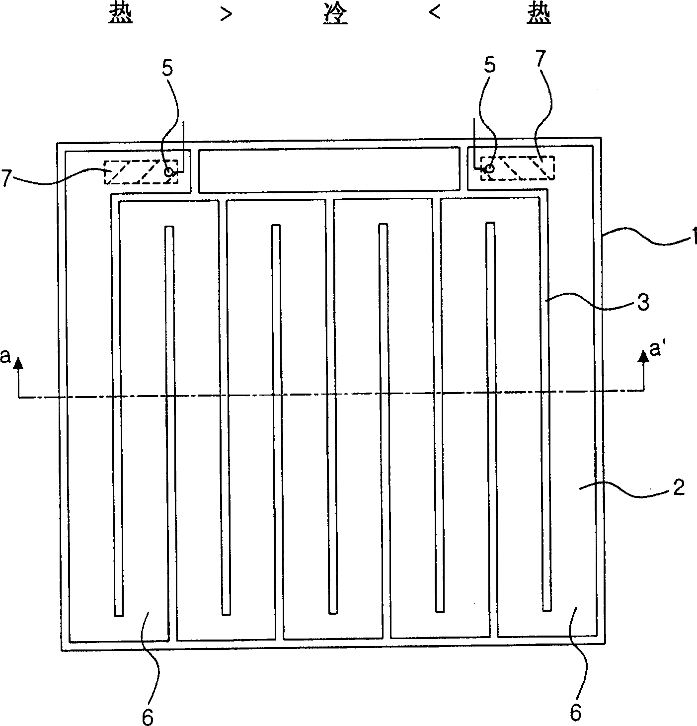
[0031] Figure 5 is a plan view showing a channel structure provided on an FFL panel of a heat-cool-heat type flat fluorescent lamp according to a first embodiment of the present invention. As shown in the figure, in the heat-cool-heat type flat fluorescent lamp according to the first embodiment of the present invention, the channel structure is specially designed so that the width of the discharge channel 16 constituting the discharge space 12 of the lamp is along the opposite direction from the lamp. The direction from the end to the middle part of the lamp forming a cold zone, which has an inner electrode 17 in an electrode chann...
PUM
 Abstract
Description
Claims
Application Information