Sartorius

A sewing machine and bottom plate technology, which is applied in the field of sewing machines, can solve problems such as malfunction, entry into the motor installed on the bottom plate frame, and decreased accuracy of rotation position detection.

Active Publication Date: 2007-01-31
BROTHER KOGYO KK
View PDF2 Cites 4 Cited by
  • Summary
  • Abstract
  • Description
  • Claims
  • Application Information

AI Technical Summary

Problems solved by technology

[0008] In the X motor and the Y motor, encoders are installed to detect the respective rotational positions in order to realize the feedback control of the feeding table driving device. If the lubricating oil entering the X motor and the Y motor adheres to the encoders, there is a detection of the rotational position. The problem of decreased accuracy
Especially when an encoder with an optical sensor is used, the attached lubricating oil will significantly reduce the detection accuracy, and there is a problem of malfunction in feedback control.
[0009] If the above-mentioned lubricating structure is adopted on the sewing machine described in Japanese Patent Publication No. 60-29992, it is the same, there is used lubricating oil from the inside of the machine arm to flow under the bottom frame and spread, and fall on the bottom frame installed on the bottom frame. Problems on the motor below
Especially in the sewing machine described in Japanese Patent Publication No. 60-29992, when the machine arm is switched from the lying position to the upright position, the lubricating oil adhering to the bottom of the base frame is likely to drip, and it is very likely to enter the sewing machine installed on the base frame. Inside the motor above, there is a problem of malfunction in the feedback control of each motor
[0010] When the lubricating oil enters the motor, it also causes the problem of deterioration of the lubricating grease of the bearing supporting the motor shaft and the rubber coating of the internal wire of the motor.

Method used


Image

  • Sartorius
  • Sartorius
  • Sartorius

Examples


Embodiment Construction

[0030] Preferred embodiments of the present invention will be described in detail below with reference to the accompanying drawings.

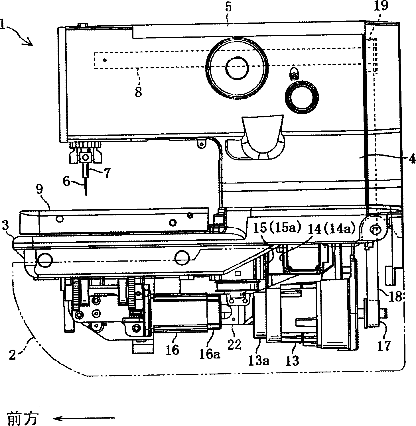
[0031] In the sewing machine of the present invention, that is, the eyelet buttonhole sewing machine shown in the figure, a partition wall is formed under the base frame to surround the discharge hole provided at the connection portion between the base frame and the column, The used lubricating oil leading out from the lower part of the frame is blocked and prevented from entering the motor arrangement area where the electric motor is arranged.

[0032] The buttonhole sewing machine 1 which is the sewing machine of the present invention will be described.

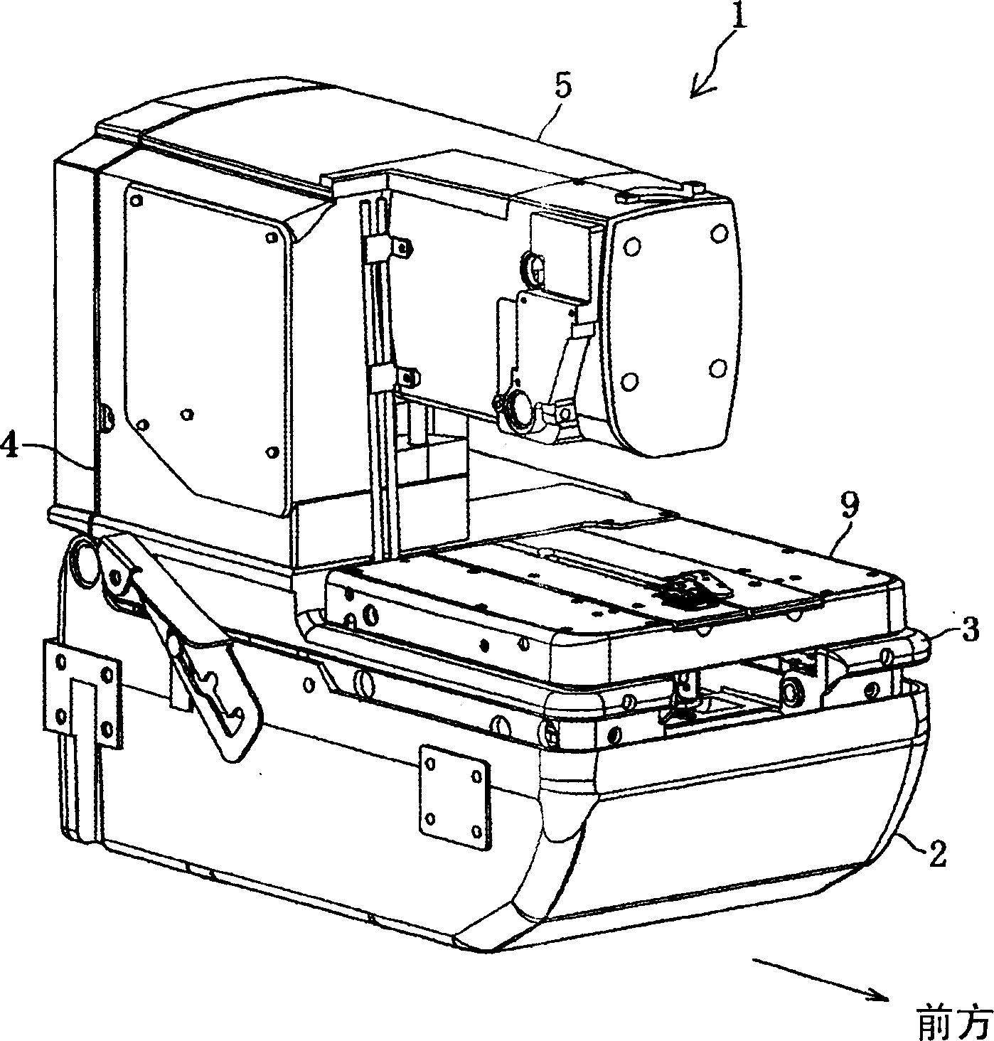
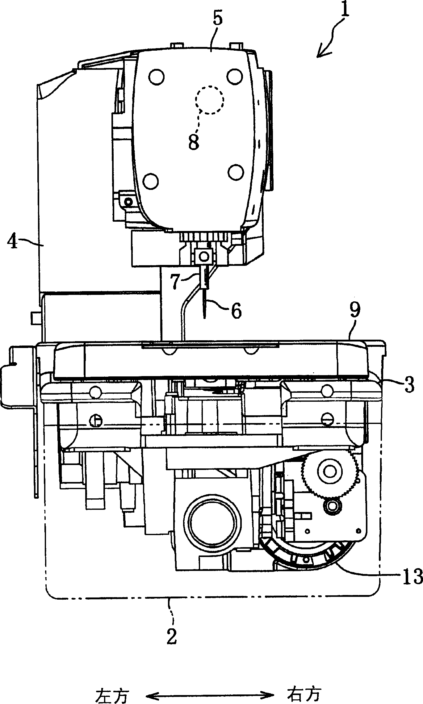
[0033] Such as Figure 1 ~ Figure 3 As shown, the round head buttonhole sewing machine 1 includes: a rectangular box-shaped machine base 2 with the upper part fully open, a base frame 3 embedded in the open part of the base 2, and a column 4 erected from the rear of the base frame 3 , and ...


PUM


Abstract

The present invention relates to a sewing machine, a motor configuration region is arranged on the different position of the discharging hole for configuring principal axis motor, X motor, Y motor, theta motor etc, wherein the discharging hole is disposed on the junction of the upright post, the area between the motor configuration region and the forming part of discharging hole is spaced by the dividing wall projecting towards downside from the bottom of the substrate frame. This arrangement prevents the used lubricating oil introduced from discharging holes from getting into the electric motor arranged in the motor configuration region.

Description

technical field [0001] The present invention relates to a sewing machine, and more particularly to a sewing machine in which an electric motor, which is a driving source of various mechanisms, is mounted in a motor mounting area provided under a chassis frame. Background technique [0002] An industrial eyelet buttonhole sewing machine for sewing eyelet eyelet stitches has: a sewing mechanism that synchronously drives a needle bar and a looper facing the needle bar; The rotating mechanism that the rod rotates around the vertical axis, and the feeding mechanism that moves the feeding table of the processed cloth in the X direction and the Y direction. According to the stitch data, the driving source of the sewing mechanism, the rotating mechanism and the feeding mechanism, that is, the electric motor, is driven and controlled, thereby forming various eyelet buttonhole stitches. [0003] The electric motors as the driving source of the feeding mechanism are an X motor and a Y...

Claims


Application Information

Patent Timeline
Patent Type & Authority Applications(China)
IPC IPC(8): D05B3/06D05B73/00
Inventor 铃木裕之清水靖宏
Owner BROTHER KOGYO KK
Why Eureka
Try Eureka