Compressed natural gas injector

A technology of compressed natural gas and injectors, which is applied in the direction of machines/engines, oil supply devices, internal combustion piston engines, etc. It can solve the problems of injectors such as unstable operation, long response time, and ejector rod breakage, and achieve good sealing and responsiveness. The effect of short time and stable work

Inactive Publication Date: 2007-01-31
BEIJING AINY ELE MECHANICAL
View PDF0 Cites 10 Cited by
  • Summary
  • Abstract
  • Description
  • Claims
  • Application Information

AI Technical Summary

Problems solved by technology

This type of injector has defects such as easy leakage between the steel ball 11 and the ball valve seat 2, breakage of the ejector rod 10, long response time, and unstable operation of the injector due to heating of the coil 5 during use.

Method used


Image

  • Compressed natural gas injector
  • Compressed natural gas injector

Examples


Embodiment Construction

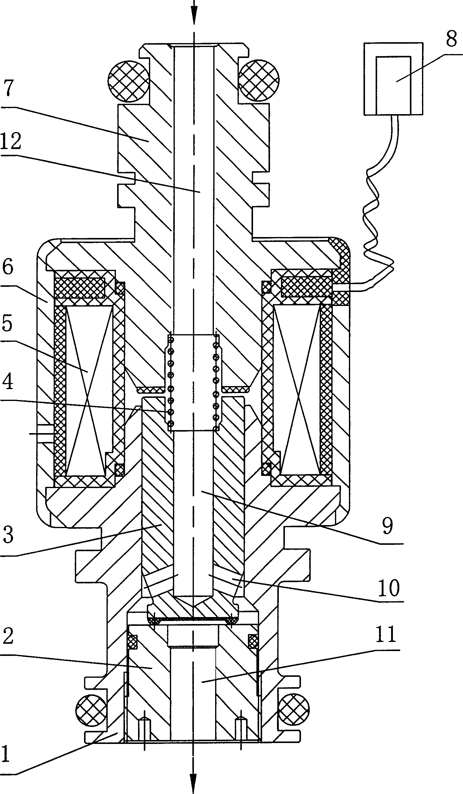
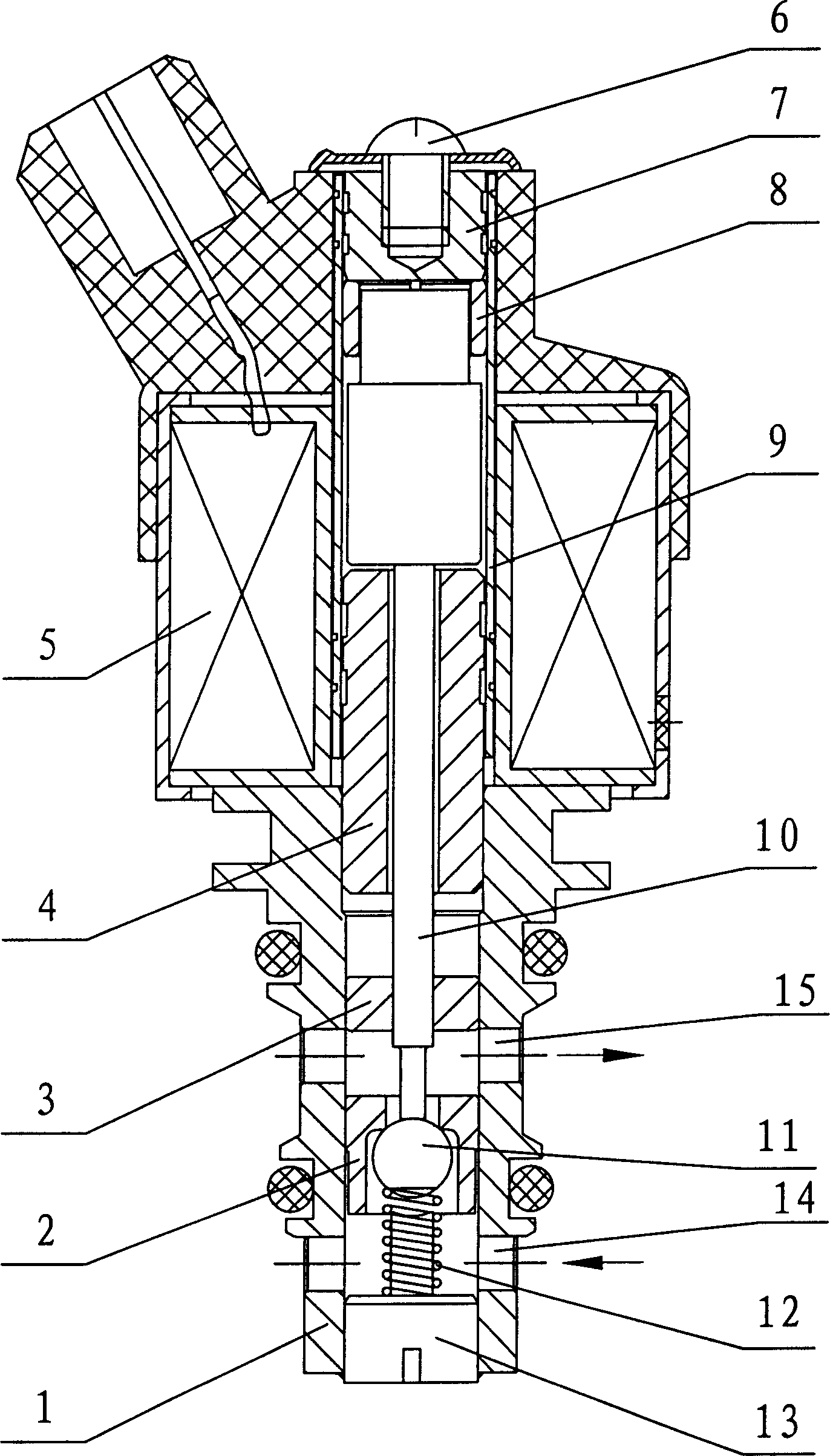
[0015] like figure 1 As shown, a compressed natural gas injector of the present invention is characterized in that it includes: an injector housing 1, a valve seat 2, an armature 3, a spring 4, a coil 5, a coil housing 6, a stop iron 7 and an electrical plug 8; The injector casing 1 and the iron stopper 7 are inserted into the hole of the coil 5, the coil casing 6 is set outside the coil 5, and the ends of the coil casing 6 are closed at both ends so that the coil casing 6, the coil 5, the iron stopper 7 and the injector casing The body 1 is connected as a whole; the valve seat 2, the armature 3 and the spring 4 are sequentially arranged in the inner hole of the injector housing 1 from bottom to top, the valve seat 2 and the injector housing 1 are screwed together, and the spring 4 tops The upper end of the armature 3; the retainer 7 is provided with an axial through hole 12, the upper end of the armature 3 is provided with an axial blind hole 9, the lower end of the armature...


PUM


Abstract

A compressed natural gas injector comprises a injector casing, a valve seat, an armature, a spring, a coil, a coil covering, a stop iron and an electric plug. The injector casing and the stop iron are inserted into the coil hole. By roll cladding and closing in of two ends of the coil covering, the coil, the coil covering, the stop iron and the injector are connected into one. The valve seat, the armature and the spring are disposed in order in the internal hole of the injector casing. There is an axial through-hole on the stop iron, an axial blind hole on top of the armature, a side hole at the bottom of the armature in communication with the axial blind hole and an axial through-hole on the valve seat. At the bottoms of the armature and the stop iron are sulphurized rubber pieces and in the internal hole of the injector casing and on the cylindrical surface of the armature are sprayed the polytetrafluoro ethylene films.

Description

technical field [0001] The invention relates to a fuel timing quantitative supply device for a compressed natural gas gas engine, in particular to a compressed natural gas injector. Background technique [0002] Using natural gas instead of oil as fuel is an ideal and feasible way to improve energy structure, reduce pollution and save costs. The injector is an important part of the engine, and its function is to supply the gas fuel to the engine in a regular and quantitative manner. The structure and working principle of the existing natural gas injectors are as follows: figure 2 As shown, it includes injector housing 1, ball valve seat 2, guide sleeve 3, pole piece 4, coil 5, fastening screw and washer 6, fixed body 7, magnetic isolation ring 8, transition sleeve 9, ejector rod 10, steel The ball 11, the spring 12 and the spring seat 13; the spring seat 13, the spring 12, the steel ball 11, the ball valve seat 2, the guide sleeve 3, the ejector rod 10, and the pole piece ...

Claims


Application Information

Patent Timeline
Patent Type & Authority Applications(China)
IPC IPC(8): F02M21/02
CPCY02T10/32Y02T10/30
Inventor 高贵方
Owner BEIJING AINY ELE MECHANICAL
Why Eureka
Try Eureka