Double system car coupler of railway vehicle

A railway vehicle, dual-system technology, applied in railway car body parts, railway couplings, transportation and packaging, etc., to achieve the effects of simplified process, improved service life and simple structure

Active Publication Date: 2007-02-07
CRRC MEISHAN
View PDF1 Cites 9 Cited by
  • Summary
  • Abstract
  • Description
  • Claims
  • Application Information

AI Technical Summary

Problems solved by technology

[0004] The double-system coupler of the railway vehicle proposed by the present invention solves the problem of the above-mentioned existing two system couplers being connected in the same railway vehicle

Method used


Image

  • Double system car coupler of railway vehicle
  • Double system car coupler of railway vehicle
  • Double system car coupler of railway vehicle

Examples


Embodiment Construction

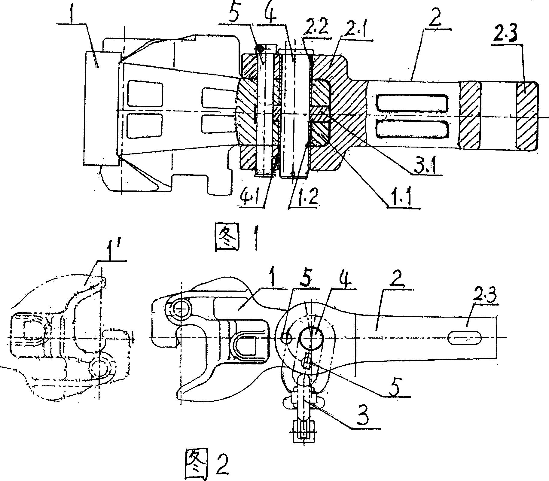
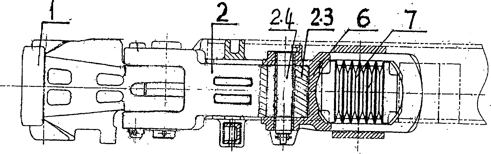
[0026] See Fig. 1, Fig. 2, the coupler of double system of railway vehicle of present embodiment is made of the bushing 4.1 of articulated coupler head 1, coupler body 2, chain coupler 3, connecting pin 4 and outer sheath, locating pin 5 etc. The U-shaped 1.1 tail end of the joint hook head 1 is inserted into the U-shaped 2.1 inner side of the front end of the hook body, and the U-shaped chain ring 3.1 of the chain coupler 3 is inserted into the U-shaped 1.1 inner side of the tail end; Movable joints. The tail-end U-shaped 1.1 and the front-end U-shaped 2.1 are respectively provided with connecting pin holes 1.2 and 2.2 for matching with the connecting pin 4 .

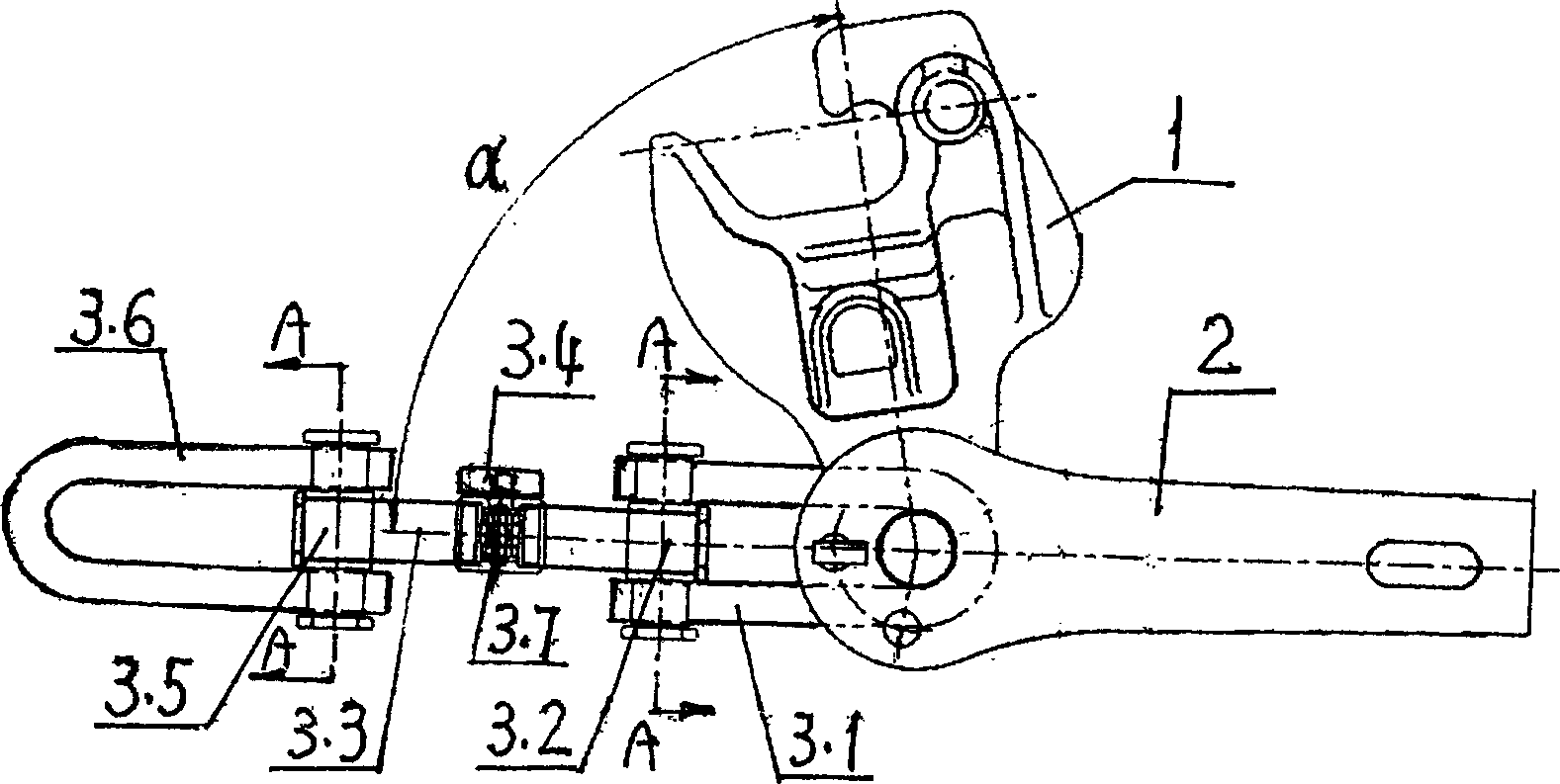
[0027] See Fig. 2, in the movable joint, when the joint head 1 rotates in the longitudinal traction direction of the vehicle, it is in the hanging working position, fixed with the positioning pin 5, and then moves along the traction direction to automatically dock with the automatic coupler 1' of the docked vehicle. N...


PUM


Abstract

The invention relates to a dual-system hook of railway train, wherein it comprises: a joint hook and hook with connecting pin hole, and two U-shaped chain hooks, while the connections between them are in U-shaped connected via connecting pins, to form the movable joint whose joint hook and chain hook can rotate; based on the hook type, it can rotate to the drawing direction, to connect two systems; the chain hook has simple structure, long service life and high reliability; and the joint hook and chain hook can meet the demands that the track heights at each track are same, and meet the demands of total load as 3000t; and the invention can use the general hook frame and national buffer of 13-th hook, to transmit the drawing force and impact force between vehicles.

Description

[0001] (1) Technical field: the present invention belongs to railway vehicle traction device. It is used for the connection between railway wagon vehicles and vehicles or between locomotives and vehicles. Transmit the longitudinal force and impact force generated by train operation or shunting operation. (two) background technology: [0002] The couplers used by existing railway vehicles are roughly divided into automatic couplers that meet the AAR standard of the North American Railway Association represented by the United States and Canada, and non-automatic couplers that meet the UIC standard of the International Union of Railways represented by European countries, that is, spiral couplers. Due to the complex operation, high working intensity and small tonnage that can be towed, the spiral coupler will be gradually eliminated, but this requires a process. In this way, it is possible to have railway vehicles equipped with two completely different coupler systems on the same...

Claims


Application Information

Patent Timeline
Patent Type & Authority Applications(China)
IPC IPC(8): B61G1/02B61G5/04
Inventor 林结良肖颖肖乾佑潘树平韦延兴
Owner CRRC MEISHAN
Why Eureka
Try Eureka