Supercharge Your Innovation With Domain-Expert AI Agents!

BTL-type amplifier circuit

一种放大电路、运算放大电路的技术,应用在放大器、低频放大器、放大器类型等方向,能够解决噪声大、不利功率放大、音质恶化等问题

Active Publication Date: 2007-02-07
KK TOSHIBA
View PDF2 Cites 10 Cited by
  • Summary
  • Abstract
  • Description
  • Claims
  • Application Information

AI Technical Summary

Problems solved by technology

[0011] However, the power amplifier with the above configuration is not conducive to power amplification with low noise or low compensation voltage because the first operational amplifier and the second operational amplifier amplify the noise or compensation voltage generated by the gm amplifier.
In particular, when the circuit with the above configuration is applied to an integrated circuit audio power amplifier, etc., if the noise is large, the sound quality will deteriorate, and if the compensation voltage is large, the POP noise will become large.

Method used


Image

  • BTL-type amplifier circuit
  • BTL-type amplifier circuit
  • BTL-type amplifier circuit

Examples


no. 1 Embodiment approach

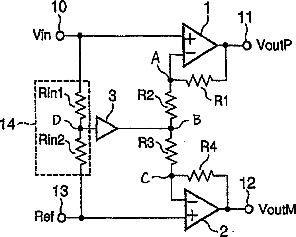
[0055] figure 1 It is a circuit diagram of the BTL power amplifier of the first embodiment of the present invention.

[0056] exist figure 1 In the BTL power amplifier, input the input voltage Vin from the signal input terminal 10 to the non-inverting input terminal (+) of the first operational amplifier (operational amplifier circuit) 1, and input the input voltage Vin from the non-inverting output terminal constituting one output terminal of the BTL power amplifier. 11 outputs an output voltage VoutP that is in phase with the input voltage Vin. A first resistance element R1 for feedback is connected between the output terminal of the operational amplifier 1 and a point A serving as an inverting input terminal (-).

[0057] Between the inverting input terminal (-) of the operational amplifier 1 and the inverting input terminal (-) of the second operational amplifier 2, a second resistive element R2 and a third resistive element R3 are connected in series.

[0058] The refe...

no. 2 Embodiment approach

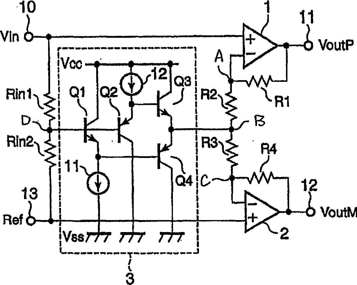
[0095] Figure 5 It is a circuit diagram of a BTL power amplifier according to the second embodiment of the present invention.

[0096] Figure 5 The BTL power amplifier shown with the reference figure 1 The BTL power amplifier of the second embodiment shown is different in that an input protection resistive element R6 is connected between the signal input terminal 10 and the non-inverting input terminal (+) of the operational amplifier 1, and an input protection resistive element R6 is connected between the Between the ground (ACGND) terminal 15 and the non-inverting input terminal (+) of the operational amplifier 2, an input protection resistive element R7 is connected, and between the reference input (Ref) terminal 13 and the AC ground terminal 15, a resistor is connected in series. Components Rin3 and Rin4.

[0097] Therefore, the impedances of the non-inverting input terminal of the operational amplifier 1 and the non-inverting input terminal of the operational amplifi...


PUM


Abstract

The invention provides an amplifier circuit of BTL system comprises a first operational amplifier 1 delivering an output signal which is in-phase with a signal inputted to a signal input terminal 11, a second operational amplifier 2 delivering an output signal having a phase reverse to that of the input signal, a voltage division circuit 14 generating the intermediate voltage of an input signal a first resistive element R1 connected between the output terminal and the reverse phase input terminal of the first operational amplifier, a second resistive element R2 and a third resistive element R3 connected in series between the reverse phase input terminal of the first operational amplifier and the reverse phase input terminal of the second operational amplifier, a fourth resistive element R4 connected between the output terminal and the reverse phase input terminal of the second operational amplifier, and an impedance conversion circuit 3 connected between the intermediate voltage node of a voltage division circuit and the series connection node the second and third resistive elements.

Description

[0001] Cross References to Related Applications [0002] This application is based upon and claims the benefit of priority from prior Japanese Patent Application No. 2005-228462 filed on August 5, 2005, the entire contents of which are incorporated herein by reference. technical field [0003] The present invention relates to an amplifying circuit, in particular to a BTL (Bridge Tied Load) power amplifier (BTL power amplifier) ​​for audio, such as a power amplifier for car audio with high output specifications. Background technique [0004] In the conventional BTL power amplifier, the input signal Vin is converted into a BTL signal current after being voltage-current converted (V-I conversion) by the gm amplifier as a preamplifier, and output to a circuit in which the first and second resistance elements are connected in series . A series connection node of the first and second resistance elements is connected to a reference input terminal. The voltage generated in the fir...

Claims


Application Information

Patent Timeline
Patent Type & Authority Applications(China)
IPC IPC(8): H03F3/181H03F3/20H03F99/00
CPCH03F3/45475H03F1/342H03F3/185H03F2200/03H03F2200/33H03F2203/45138H03F2203/45528
Inventor 鹤见博幸
Owner KK TOSHIBA
Features
  • R&D
  • Intellectual Property
  • Life Sciences
  • Materials
  • Tech Scout
  • Unparalleled Data Quality
  • Higher Quality Content
  • 60% Fewer Hallucinations
Learn More