Electric leakage detecting apparatus

a leakage detection and apparatus technology, applied in the field of electric leakage detection apparatuses, can solve the problems of increased apparatus costs and possible degradation of batteries, and achieve the effect of reducing the cost of apparatuses and inhibiting the degradation of batteries

Inactive Publication Date: 2014-01-23
KEIHIN CORP
View PDF6 Cites 38 Cited by
  • Summary
  • Abstract
  • Description
  • Claims
  • Application Information

AI Technical Summary

Benefits of technology

[0017]That is to say, according to the aspects of the present invention, it becomes possible to inhibit the d

Problems solved by technology

In the technique described in Japanese Unexamined Patent Application, First Publication No. 2011-102788, high voltage resistance circuit components become necessary the more the output voltage of the battery become

Method used


Image

  • Electric leakage detecting apparatus
  • Electric leakage detecting apparatus
  • Electric leakage detecting apparatus

Examples


Embodiment Construction

[0023]Herein, an embodiment of the present invention is described with reference to the drawings.

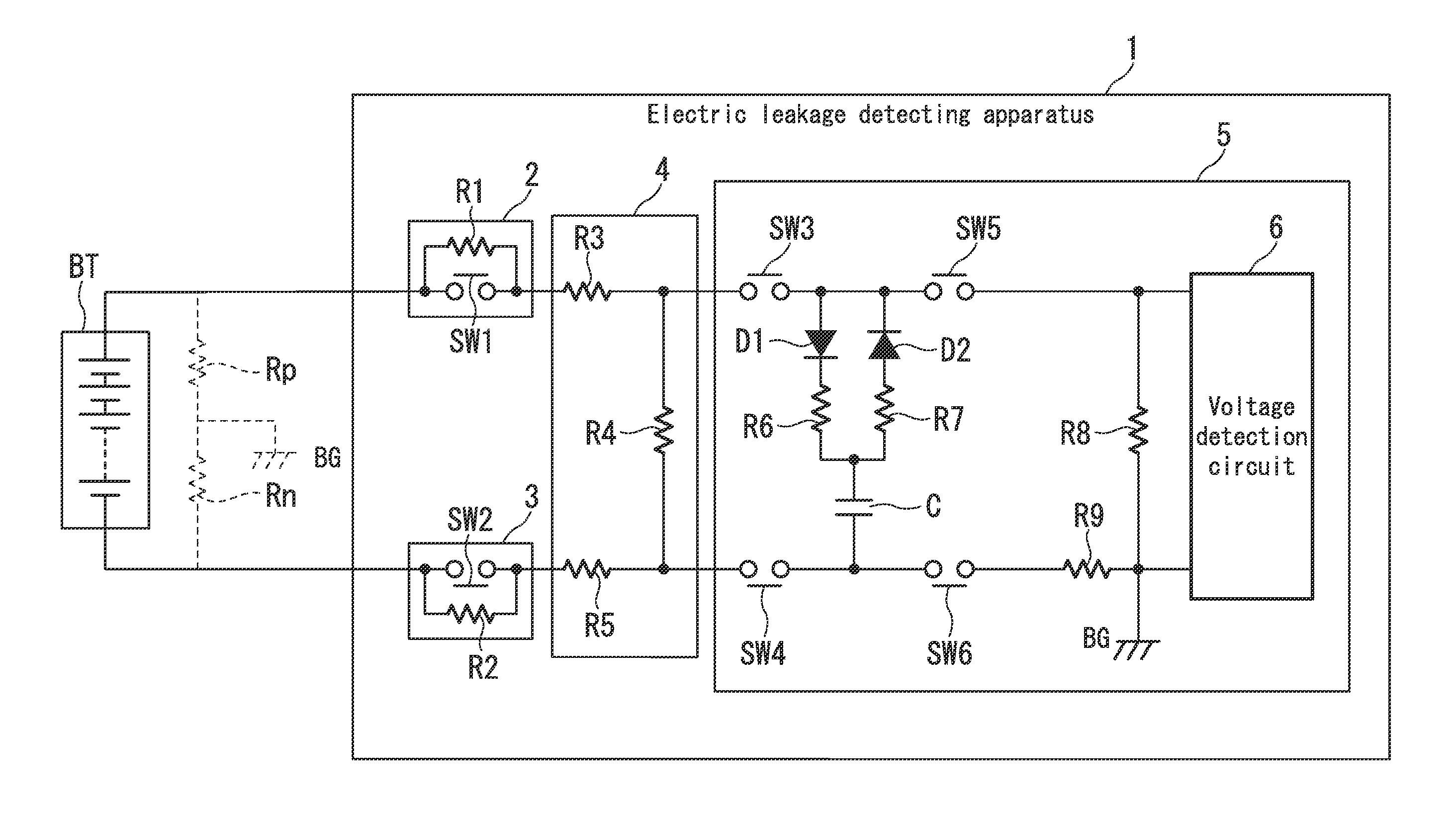
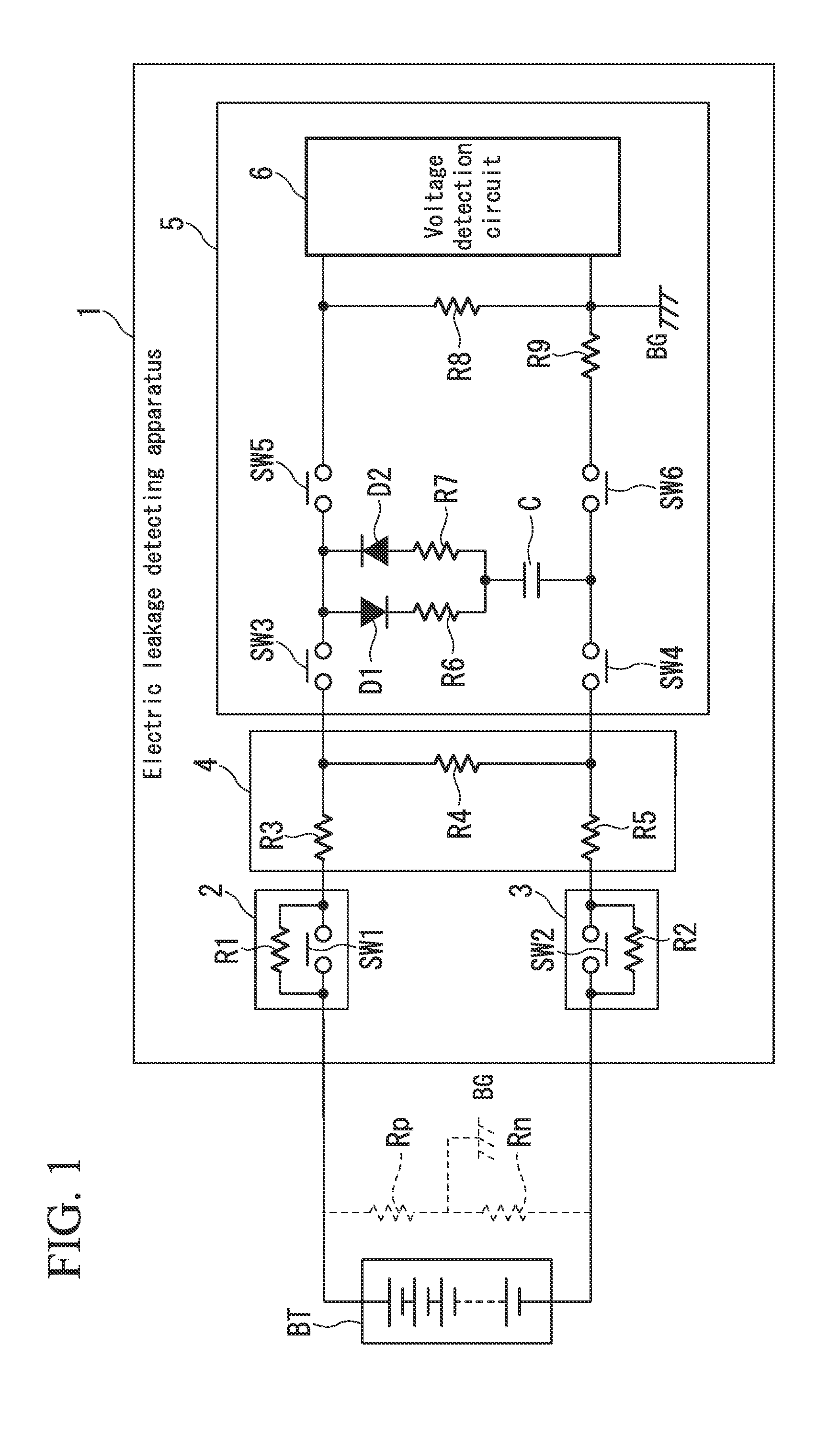
[0024]FIG. 1 is a schematic block diagram of an electric leakage detecting apparatus 1 according to the present embodiment. The electric leakage detecting apparatus 1 is one that detects electric leakages of a high voltage battery BT (a battery with a rated voltage of 900 V for example) for driving a motor that is insulated from a chassis ground BG, and is provided with a first dark current inhibit circuit 2, a second dark current inhibit circuit 3, a voltage dividing circuit 4, and an electric leakage determining circuit 5.

[0025]The first dark current inhibit circuit 2 is constituted by a switch SW1 with one end connected to the positive terminal of the high voltage battery BT and the other end connected to the voltage dividing circuit 4 (specifically a resistance R3 mentioned below), and a resistance R1 connected in parallel to the switch SW1. The second dark current inhibit circuit 3 ...


PUM


Abstract

An electric leakage detecting apparatus, in an electric leakage detecting apparatus which is insulated from a chassis ground and detects electric leakages of a battery, is provided with: a voltage dividing circuit that divides an output voltage of the battery; an electric leakage determining circuit provided at a rear stage of the voltage dividing circuit, that determines the presence of an electric leakage based on a voltage detected by a circuit that respectively connects to a positive electrode side insulation resistance or a negative electrode side insulation resistance of the battery; and a dark current inhibit circuit in which a switch and a resistance are connected in parallel, that is inserted between at least either one of wiring that connects a positive terminal of the battery and the voltage dividing circuit, and wiring that connects a negative terminal of the battery and the voltage dividing circuit.

Description

CROSS-REFERENCE TO RELATED APPLICATION[0001]Priority is claimed on Japanese Patent Application No. 2012-159699, filed Jul. 18, 2012, the content of which is incorporated herein by reference.BACKGROUND[0002]1. Field of the Invention[0003]The present invention relates to an electric leakage detecting apparatus.[0004]2. Description of Related Art[0005]As is well known, vehicles such as electric vehicles and hybrid vehicles are equipped with a motor, which becomes the source of power, and a high voltage and large capacity battery that supplies electric power to the motor. The high voltage battery is one configured by serially connecting a plurality of battery cells comprising lithium ion batteries or hydrogen nickel batteries, or the like.[0006]Such high voltage batteries for driving a motor are insulated from the chassis ground for safety. Therefore, it is very important to monitor the insulated state (or in other words, to detect electric leakages) between the high voltage battery and...

Claims


Application Information

Patent Timeline
IPC IPC(8): G01R31/02
CPCG01R31/025G01R31/382G01R31/52
Inventor YAMADA, TAKESHIABE, HIDEFUMI
Owner KEIHIN CORP
Why Eureka
Try Eureka