Method and system for cooling at least one electronic device

A technology for electronic devices and devices, which is applied in the field of cooling at least one electronic device, can solve the problems of low cooling amount, hinder the operation of electronic devices, etc., and achieve the effect of preventing interference

Inactive Publication Date: 2007-02-07
KONINK PHILIPS ELECTRONICS NV
View PDF1 Cites 2 Cited by
  • Summary
  • Abstract
  • Description
  • Claims
  • Application Information

AI Technical Summary

Problems solved by technology

The resulting electromagnetic radiation may interfere with the operation of electronic devices
Furthermore, the amount of cooling provided by known methods is relatively low

Method used


Image

  • Method and system for cooling at least one electronic device
  • Method and system for cooling at least one electronic device
  • Method and system for cooling at least one electronic device

Examples


Embodiment Construction

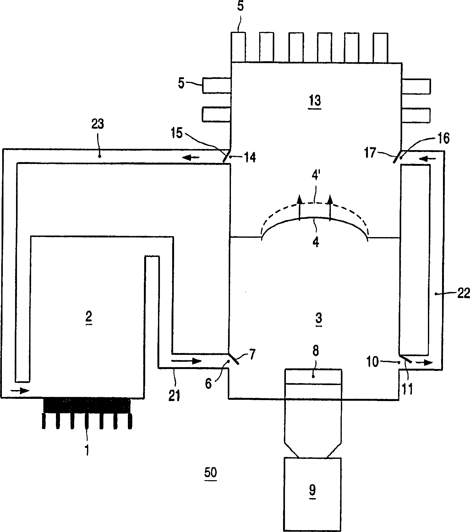
[0022] figure 1 A system for cooling an electronic device 1 is shown. The electronic device 1 may be, for example, a semiconductor device, a device including one or more amplifying components, a microelectronic device, an integrated circuit, a chip, a high current component, a resistor and / or any other electronic or electrical device that may generate heat during operation. device. The system is part of an electronic product 50 .

[0023] The electronic device 1 is mounted on the heat collecting chamber 2 . The heat collection chamber 2 is filled with a suitable heat transfer fluid comprising, for example, one or more liquids and / or gases. In an advantageous embodiment, the fluid is or comprises air, since air is cheap and safe to use. Optionally, the fluid may comprise, for example, one or more refrigerants such as chlorofluorocarbons (CFCs), hydrofluorocarbons (HCFCs) or similar refrigerant substances. The electronic device 1 is preferably mounted in such a way that the...


PUM


Abstract

A method of cooling at least one electronic device is described, wherein a movable pumping element (4) pumps a fluid to and / or from said device, and wherein the movement of said pumping element (4) is induced by heat. A system for cooling at least one electronic device is described, comprising at least one movable pumping element (4) for transporting a fluid to and / or from said device, wherein said pumping element (4) is movable by heat.

Description

technical field [0001] The invention relates to a method of cooling at least one electronic device. [0002] The invention also relates to a system for cooling at least one electronic device. Background technique [0003] A method and a system for cooling electronic components are known from European patent application EP-A 1 020 911. In known methods and systems, a housing is mounted on a heat sink of an electronic device. The case contains a vibrating plate to move air through the case so that the air cools the heat sink of the electronics. The vibrating piece is driven by an electromagnet. [0004] A disadvantage of the known method is that it requires relatively large amounts of energy. Also the heat generated by the electronics is wasted. In known methods and systems, electromagnets are used to drive the vibrating plate. The resulting electromagnetic radiation may interfere with the operation of electronic devices. Furthermore, the amount of cooling provided by k...

Claims


Application Information

Patent Timeline
Patent Type & Authority Applications(China)
IPC IPC(8): H01L23/46H01L23/467H01L23/473F04B43/04F04B19/24F04B43/02F04B53/08
CPCF04B43/043H01L23/473F04B53/08H01L2924/0002F04B19/24F04B43/02H01L2924/00H05K7/20
Inventor R·索格哈尔
Owner KONINK PHILIPS ELECTRONICS NV
Why Eureka
Try Eureka