

Construction method of high quality relief well
A construction method and a technology of relief wells, which are applied in infrastructure engineering, dikes, coastline protection, etc., can solve the problems of difficulty in cleaning the mud in the hole, high construction cost, laborious and other problems, so as to reduce the construction cost, The effect of simple construction, time-saving and labor-saving construction
Inactive Publication Date: 2007-02-14
GUANGDONG NO 2 HYDROPOWER ENGINEERING COMPANY LTD
View PDF0 Cites 5 Cited by
- Summary
- Abstract
- Description
- Claims
- Application Information
AI Technical Summary
Problems solved by technology
However, after the installation of the piezometric tube and the construction of the filter layer in the pressure relief well for the mud protection hole, there are problems of cleaning the mud in the hole and removing the mud skin on the hole wall. It needs to be flushed with circulating water for a long time to meet the quality requirements, which is time-consuming and cost-effective. Laborious and high construction cost
Method used
View moreImage
Smart ImageViewing Examples

Examples
Embodiment Construction
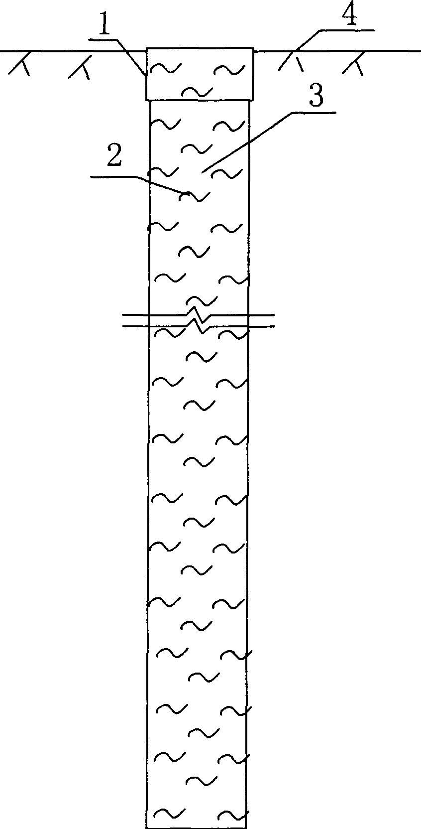
[0012] 1. Drilling construction of decompression well: reverse circulation drilling construction, directly use high-performance stable fluid to protect the hole; direct circulation drilling construction, first use mud wall to drill, and use high-performance stable fluid to replace protection after reaching the designed drilling depth Hole mud, and remove the mud skin on the hole wall; after cleaning the hole, use high-performance stabilizing fluid to protect the hole.
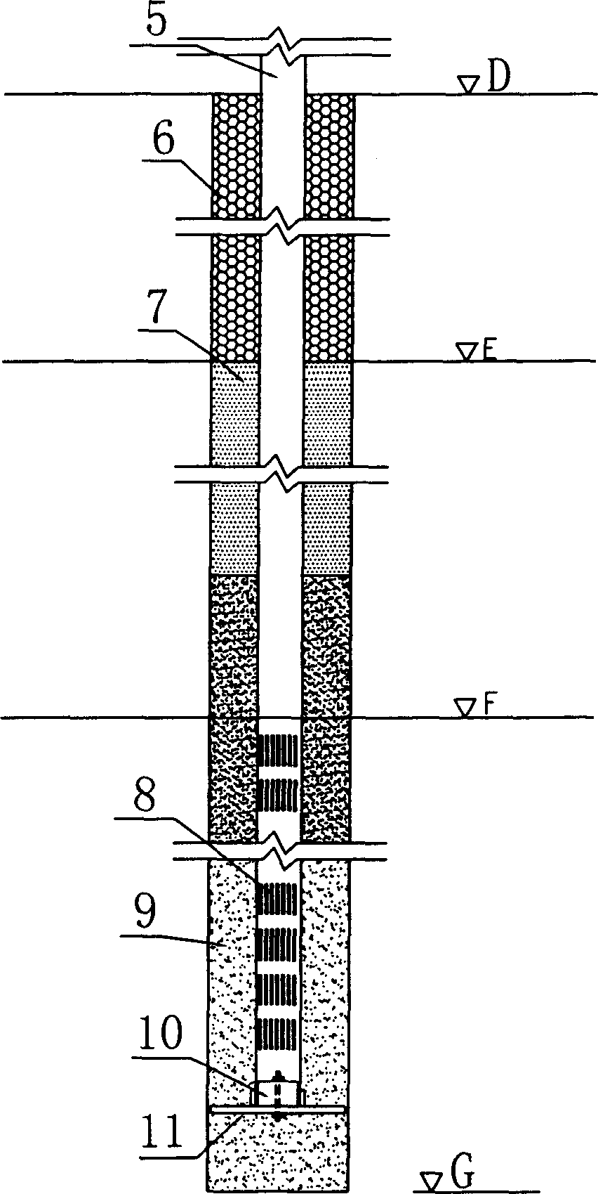
[0013] 2. Install and fix the drainage pipe of the relief well.
[0014] 3. Construction of pressure relief well filter material and other fillers.
[0015] 4. Relief well pumping, cleaning, and other follow-up work.
Login to View More PUM
 Abstract
A method for constructing relief well in high quality includes applying positive circulation to drill hole, using slurry as retainer of hole and hole wall, using high quality of stabilizing liquid to replace slurry as retainer of hole and removing off mud skin on hole wall after designed depth of hole is reached then applying high quality of stabilizing liquid as retainer of complete hole after said mud skin on hole wall is removed off.
Description
Technical field [0001] The invention relates to the treatment of permeable embankment foundations of water conservancy projects, in particular to a construction method for high-quality relief wells. Background technique [0002] The treatment of permeable embankment foundations in water conservancy projects often adopts the method of constructing relief wells and building relief ditches for centralized drainage and pressure relief to prevent piping in embankment foundations. The construction of relief wells often adopts mud retaining wall drilling to ensure that the hole wall does not collapse during the pore-making process, the installation of drainage pipes for relief wells, and the construction of filter layers. However, after the installation of the piezometric tube and the construction of the filter layer in the pressure relief well for the mud protection hole, there are problems of cleaning the mud in the hole and removing the mud skin on the hole wall. It needs to be ...
Claims
Login to View More Application Information
Patent Timeline
 IPC IPC(8): E02B3/10E02D19/20
Inventor丘宏余丁仕辉卓寒清
OwnerGUANGDONG NO 2 HYDROPOWER ENGINEERING COMPANY LTD