
Electrical connector

一种电连接器、连接器的技术,应用在连接、固定连接、电路等方向,能够解决提高制造成本、不能端子原封不动、连接器大型化等问题,达到容易制造、制造成本低、弹性变形容易的效果

Active Publication Date: 2007-02-14
HIROSE ELECTRIC GROUP
View PDF2 Cites 13 Cited by
  • Summary
  • Abstract
  • Description
  • Claims
  • Application Information

AI Technical Summary

Problems solved by technology

This can lead to a large connector size
In order to avoid upsizing, it is necessary to make a complicated and curved wrist to substantially increase the length of the wrist, which will further increase the manufacturing cost
[0008] However, the terminal of the connector of Patent Document 2 cannot be used as it is in the invention of Patent Document 1, which achieves the purpose of achieving both cost and sufficient elasticity by changing the processing direction of the metal plate.

Method used


Image

  • Electrical connector
  • Electrical connector
  • Electrical connector

Examples


Embodiment Construction

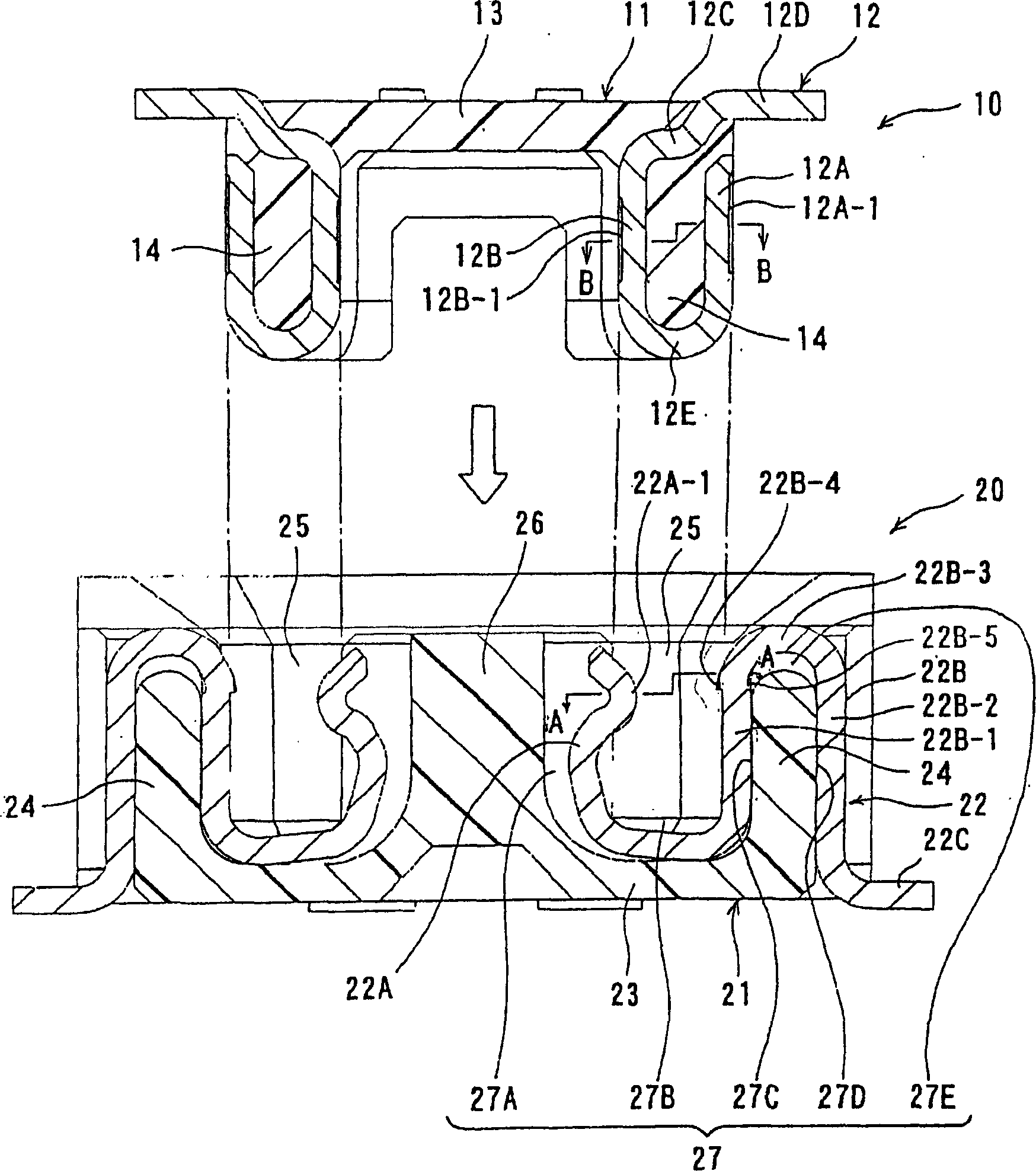
[0029] Below, according to figure 1 ~ Figure 3 illustrates an embodiment of the present invention.

[0030] figure 1 It is a cross-sectional view showing the male connector 10 and the female connector 20 that are connected to each other.

[0031] The male connector 10 has a housing 11 made of synthetic resin as an electrical insulating member, and a terminal 12 processed from a metal plate, and the terminal 12 is held by being integrally molded with the housing 11.

[0032] In the housing 11, two terminal holding wall portions 14 are formed upright from the base wall portion 13 with a predetermined interval therebetween. The distance between the two opposite inner wall portions of the two terminal holding wall portions 14 is set to be approximately the same as the thickness of the center wall portion of the target connector, that is, the female connector 20 described later. The distance between the two outer wall portions of the holding wall portion 14 is set to be approximatel...


PUM


Abstract

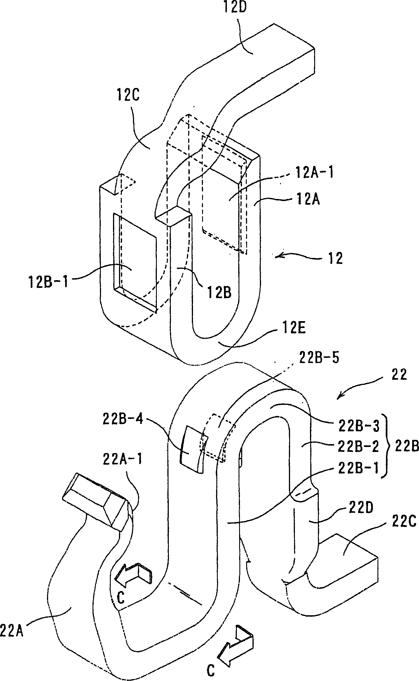
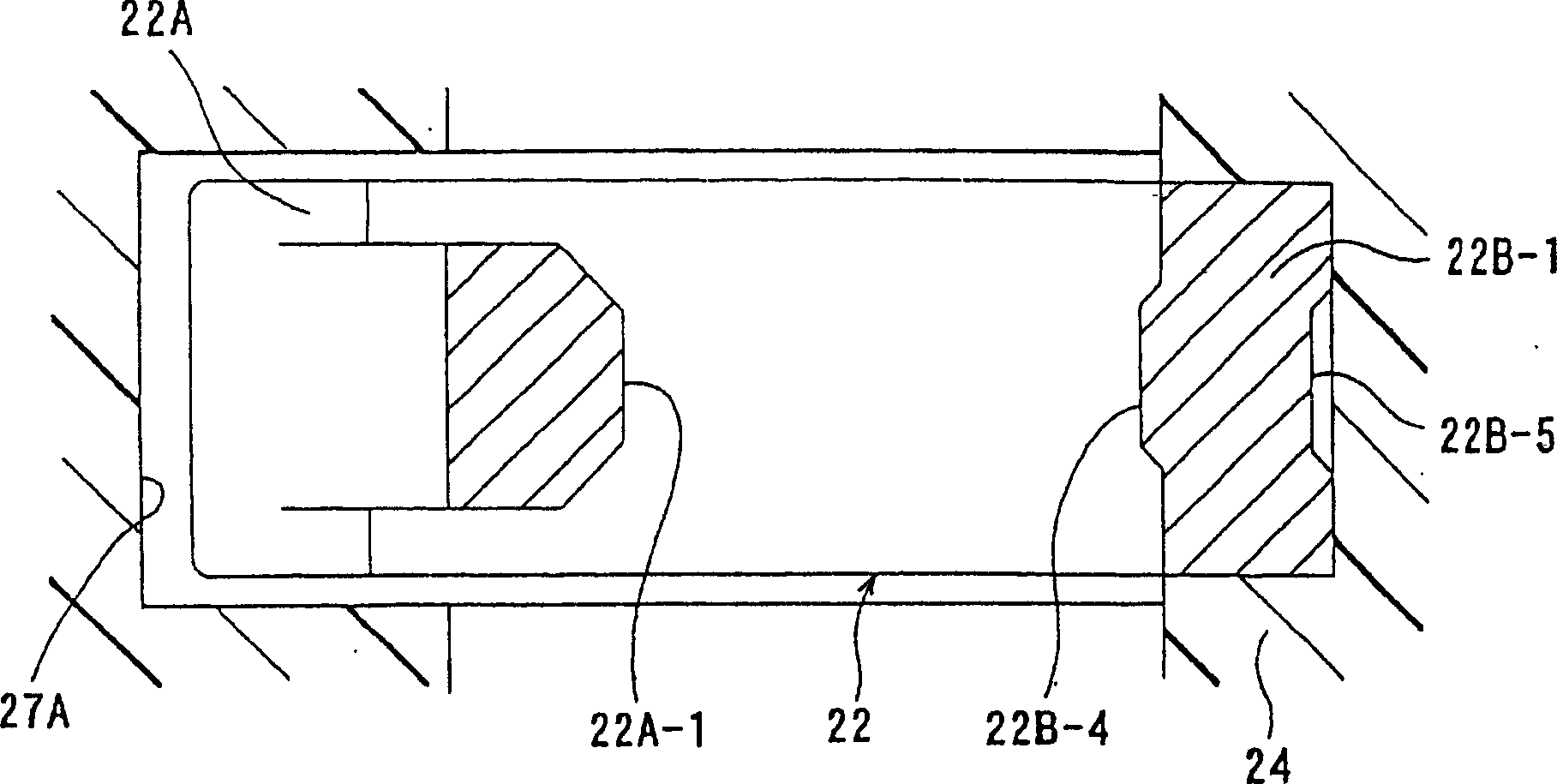
The terminals of a pair of connectors are made by deforming sheet metal in the thicknesswise direction so that they are located within an interference area prior to connection. The terminal (12) of a connector (10) has a flat indentation (12B-1), while the terminal (22) of another connector (20) has a projection (22A-1) within an area corresponding to the flat indentation (12B-1). The flat indentation (12B-1) and the projection (22A-1) are located within the interference area upon connection.

Description

Technical field [0001] The present invention relates to electrical connectors. Background technique [0002] On a pair of connectors that are mated and connected to each other, ensure that the contact area between the two connector terminals is large to make it conductive. Therefore, it is best that the terminals of the two connectors are on the plate of the metal plate. The surface is provided with a contact part. [0003] Two connectors having such terminals are disclosed in Patent Document 1, for example. The terminal of the connector of Patent Document 1 is bent in the thickness direction of the metal plate, is easy to process, and can sufficiently ensure elasticity for contact. However, since there is no countermeasure for the deviation of the contact position (especially in the width direction of the terminal), the contact will be incomplete due to the deviation, and it is not easy to reduce the pitch of the terminal arrangement. In addition, when an electronic device carry...

Claims


Application Information

Patent Timeline
Patent Type & Authority Applications(China)
IPC IPC(8): H01R12/16H01R12/32
CPCH01R12/714H01R13/20H01R12/57H01R12/716H01R12/73H01R12/55
Inventor 绿川和弥
Owner HIROSE ELECTRIC GROUP
Learn More