Eccentric swing type planetary gear device

A planetary gear, eccentric swing technology, applied in the direction of gear transmission, transmission, belt/chain/gear, etc., can solve the problems of shortened life of external tooth 101 tooth surface, unable to fully increase output torque, low rigidity, etc. The effect of increasing the natural vibration frequency, improving the vibration characteristics and controllability, and prolonging the life of the tooth surface

Active Publication Date: 2007-02-14
NABLESCO CORP
View PDF2 Cites 22 Cited by
  • Summary
  • Abstract
  • Description
  • Claims
  • Application Information

AI Technical Summary

Problems solved by technology

Here, since the bridge portion 105 on the external gear 104 located on the radially outer side of the through hole 103 has a thinner wall thickness than other parts, the rigidity is low. The normal direction of 103 acts on the bridge 105 with low rigidity in a direction substantially perpendicular to the extending direction of the bridge 105, so that the bridge 105 and the external teeth 101 near the bridge 105 are elastic. Deformation, the outer teeth 101 contact one end of the inner teeth (roller) 102, and there is a problem that the tooth surface life of the outer teeth 101 is shortened
[0012] Furthermore, in order to prevent the tooth tops of the external teeth from interfering with the inner circumference of the internal gear, the externally toothed gear is obtained by dividing the position of the above-mentioned converging point (distance in the radial direction from the center of the internal gear) by the number of internal teeth (rollers). The amount of eccentricity relative to the internal gear must be less than 0.5 times the radius of the internal tooth (roller) (about 0.40 to 0.45 times in conventional planetary gear units). Outward movement is limited, and there is a problem that the output torque cannot be increased sufficiently

Method used


Image

  • Eccentric swing type planetary gear device
  • Eccentric swing type planetary gear device
  • Eccentric swing type planetary gear device

Examples


Embodiment 1

[0057] Embodiment 1 of the present invention will be described below with reference to the drawings.

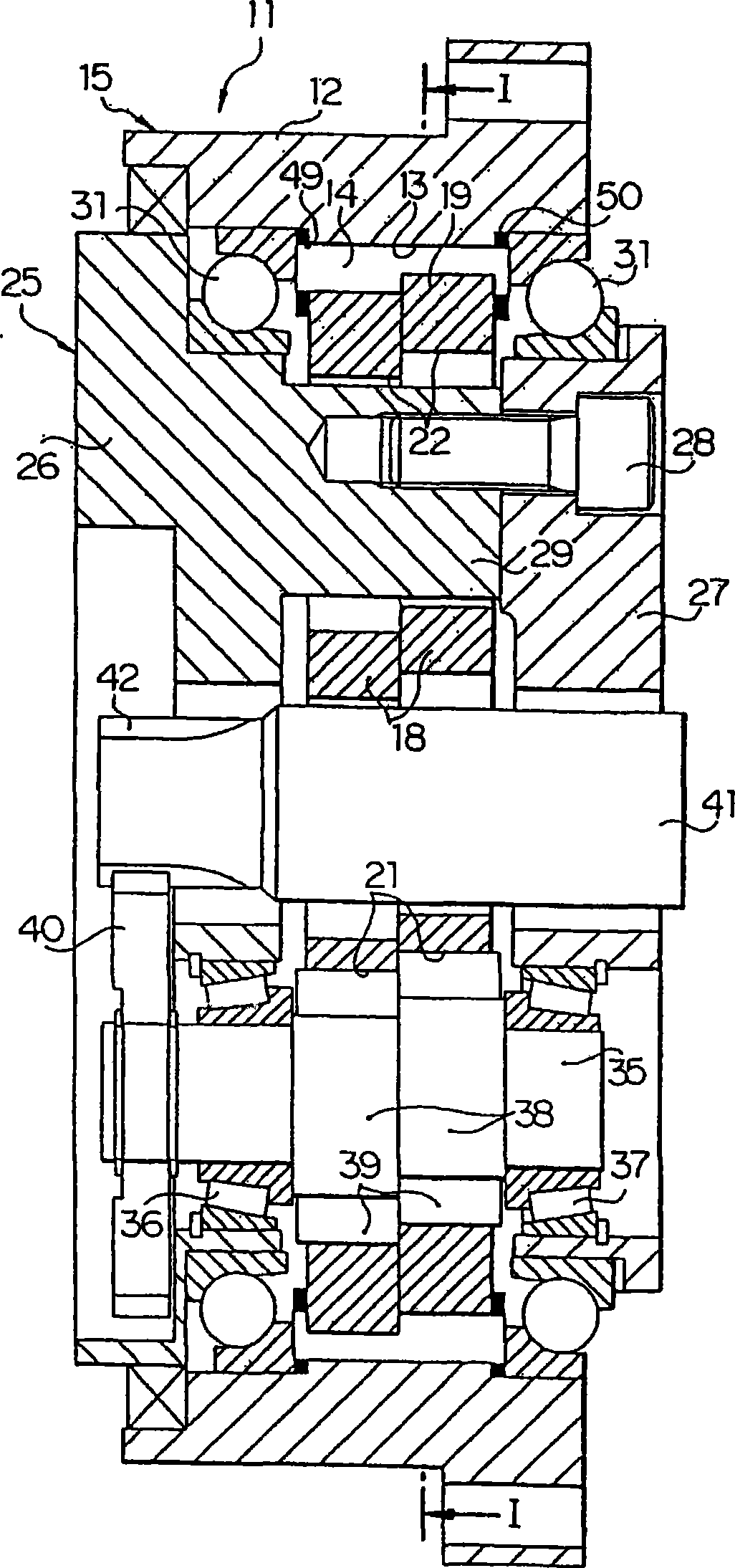
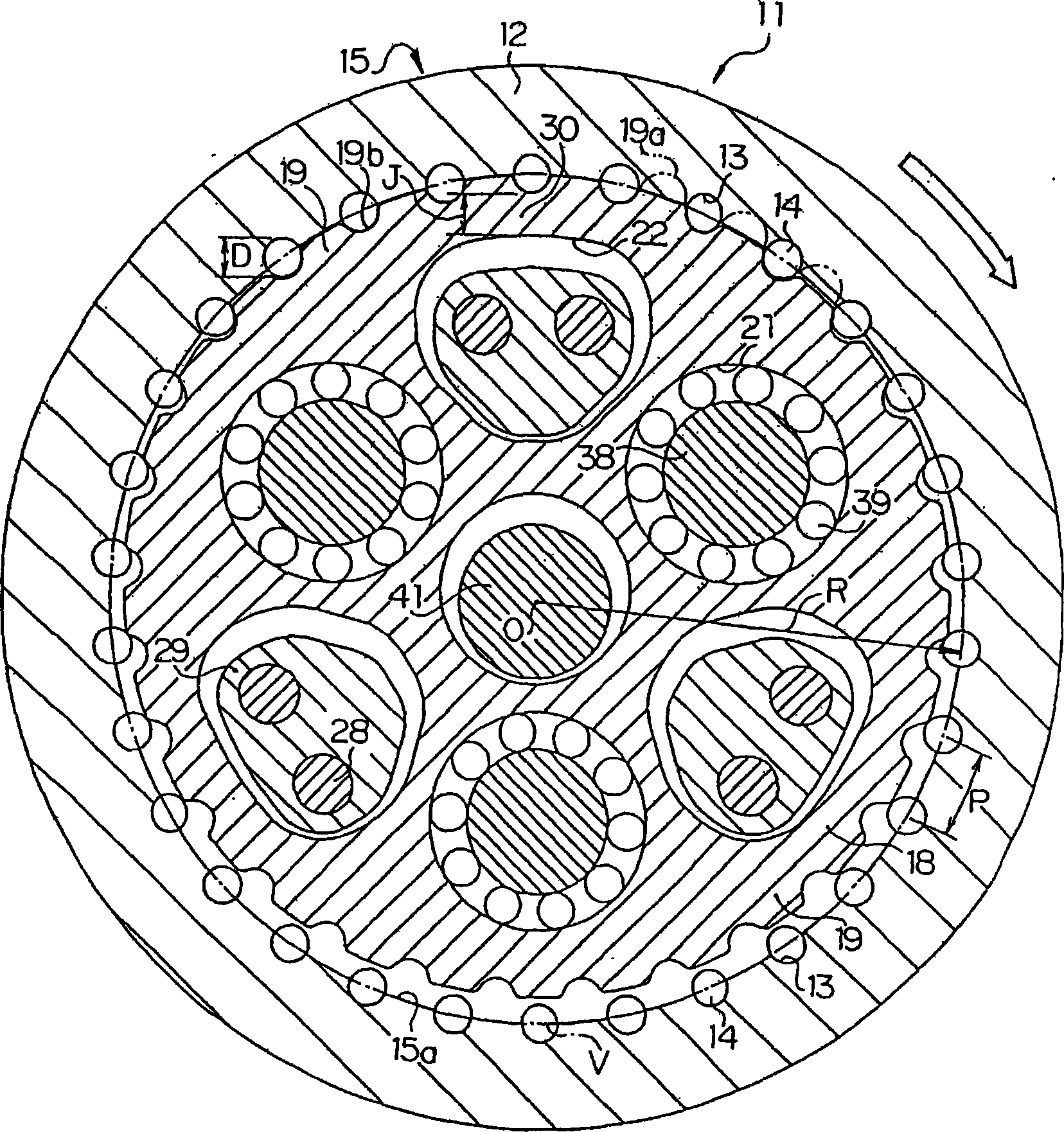
[0058] exist figure 1 , figure 2 Among them, 11 is an eccentric oscillating planetary gear device used in a robot or the like, and the planetary gear device 11 has a substantially cylindrical rotating housing 12 attached to, for example, an arm or hand of a robot not shown in the figure. A plurality of roller (pin) grooves 13 having a semicircular cross-section at the central portion in the axial direction are formed on the inner periphery of the rotating housing 12. These roller grooves 13 extend in the axial direction and are separated at equal distances in the circumferential direction. It is arranged separately with a certain tooth pitch P. 14 is an internal tooth composed of a plurality of cylindrical rollers (the same number as the roller grooves 13), and approximately half of these internal teeth (rollers) 14 are inserted into the roller groove 13, so that Equidis...

Embodiment 2

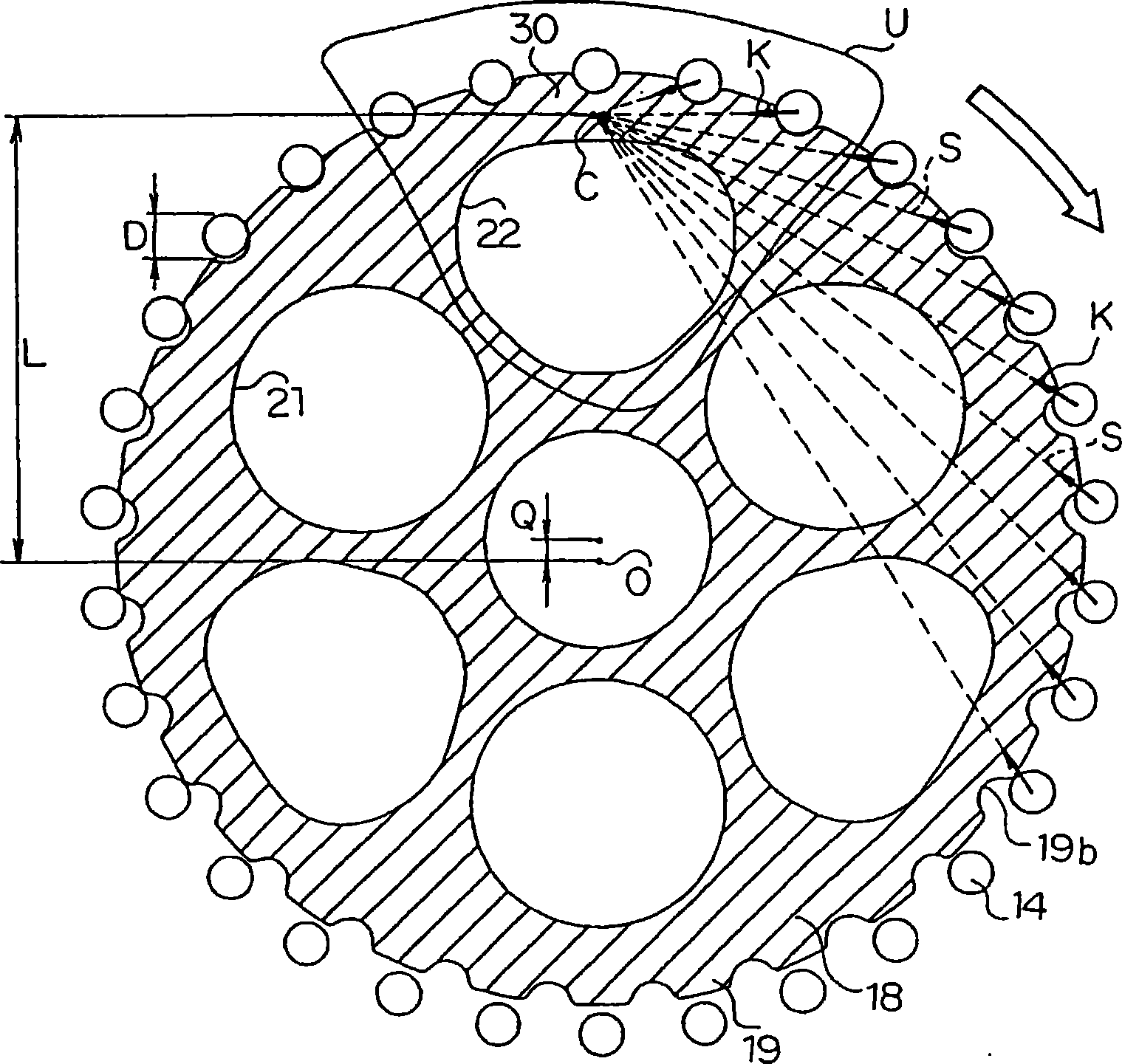
[0091] Figure 7 , 8It is a figure which shows Example 2 of this invention. In this second embodiment, the outer teeth 19 are not removed as in the first embodiment, but the inner circumference of the internal gear 15 (rotary casing 12) between adjacent internal teeth (rollers) 14 and the inner circumference of each The inner circumference around the inner teeth (roller) 14 is cut off to a depth greater than the amount by which the outer teeth 19 exceed the inner circumference. This avoids interference between the external teeth 19 and the inner periphery 15a of the internal gear 15 (rotary casing 12) after removal.

[0092] As a result, the radially outer end of each internal tooth (roller) 14 is in line contact with the inner periphery 15a of the internal gear 15 after removal, whereby the rotating housing 12 receives the driving force component acting on each internal tooth (roller) 14 The force component in the radial direction of . At this time, since there is no roll...

Embodiment 3

[0096] Embodiment 3 of the present invention will be described below with reference to the drawings.

[0097] exist Figure 9 , 10 In , 11, 111 is an eccentric oscillating planetary gear device for a robot or the like, and the planetary gear device 111 has a substantially cylindrical rotating housing 112 mounted on an arm, hand, etc. of a robot not shown in the figure. A plurality of roller grooves 113 having a semicircular cross-section at the central portion in the axial direction are formed on the inner periphery of the rotary housing 112 , and the roller grooves 113 extend in the axial direction and are arranged at equal distances in the circumferential direction. 114 is an internal tooth composed of a plurality (the same number as the roller groove 113) of cylindrical rollers, and about half of these internal teeth (rollers) 114 are inserted into the roller groove 113, so they are spaced apart in the circumferential direction, etc. The distance is set on the inner circu...


PUM


Abstract

The invention provides eccentric swing type planetary gear device, deformation of bridge sections in an externally toothed gear and of outer teeth is suppressed, and this extends the life of tooth surfaces of external teeth (19), improves vibration characteristics, and drastically increases output torque while preventing a planetary gear device (11) from becoming large in size. To achieve the above, a ratio obtained by dividing the diameter (D) of pins constructing internal teeth (14) by the pitch (P) of the internal teeth (14) is made smaller to an extent where the tooth tops (19a) of the external teeth (19) are radially outside the inner periphery (15a) of an internally toothed gear (15), or alternatively, a meeting point (C) where the lines (S) of action of reaction forces (K) as drive force components meet is moved more radially outward than a conventional position so as to be positioned between a pin circle (P) passing the centers of all the internal teeth (pins) (14) and an outer end passing circle (G) passing radially outer ends of through-holes (22), or further alternatively, the amount (H) of eccentricity of an externally toothed gear (18) relative to an internally toothed gear is set not less than 0.5 times the radius (R) of the internal teeth (pins)(14).

Description

technical field [0001] The present invention relates to an eccentric oscillating planetary gear device, which eccentrically oscillates an external gear meshed with an internal gear through a crankshaft. Background technique [0002] As a conventional eccentric oscillating planetary gear device, for example, a device described in Patent Document 1 is known. [0003] The device is provided with: an internal gear with a plurality of cylindrical rollers arranged at a certain pitch on the inner circumference; an external gear with a plurality of crank shaft holes and through holes, and a trochoid on the outer circumference. The external teeth formed by the tooth shape mesh with the above-mentioned internal teeth and the number of teeth is only one less than the internal teeth; the crankshaft is inserted into each crankshaft hole, and the external gear is eccentrically oscillated by rotation; the support body can rotatably support the above-mentioned The crankshaft also has a plu...

Claims


Application Information

Patent Timeline
Patent Type & Authority Applications(China)
IPC IPC(8): F16H1/32
Inventor 藤本宪一
Owner NABLESCO CORP
Why Eureka
Try Eureka