Soft starter for big powered electrical motor with built in bypass

A soft starter, high-power technology, applied in the direction of a single polyphase induction motor starter, motor generator/starter, etc., can solve the problems of difficult installation, unsuitability, high noise, etc.

A soft starter, high-power technology, applied in the direction of a single polyphase induction motor starter, motor generator/starter, etc., can solve the problems of difficult installation, unsuitability, high noise, etc.

CN1917353AInactive Publication Date: 2007-02-21SHANGHAI JIUKANG ELECTRIC

Image

  • Soft starter for big powered electrical motor with built in bypass
  • Soft starter for big powered electrical motor with built in bypass
  • Soft starter for big powered electrical motor with built in bypass

Examples


Embodiment Construction

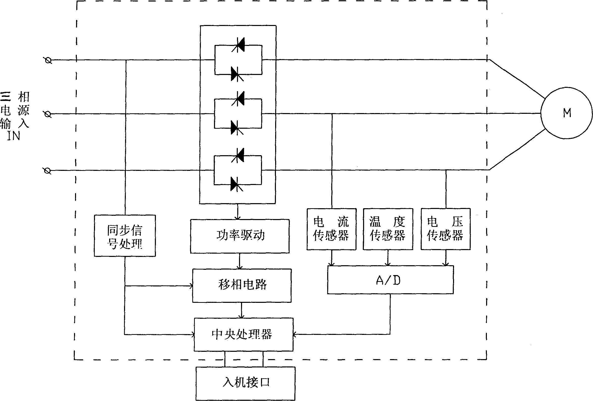
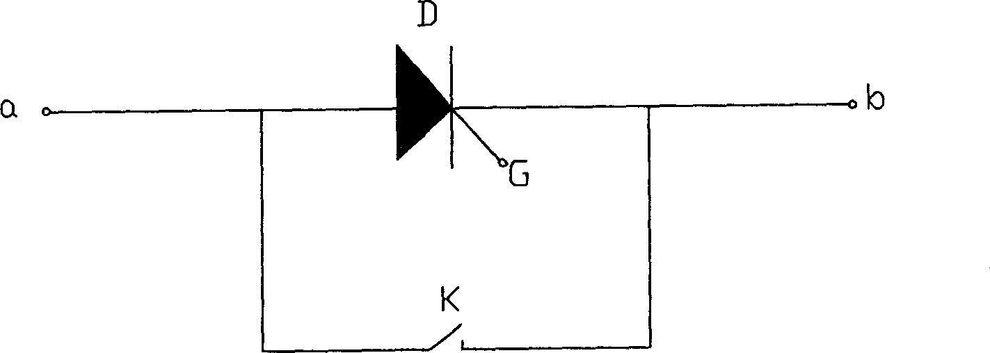
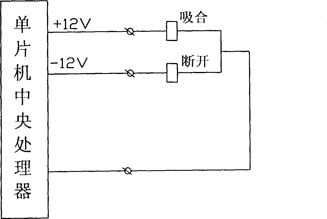
[0011] Such as figure 1 , figure 2 , image 3 , Figure 4 As shown, this embodiment includes a single-chip central processing unit, a thyristor and its control circuit, and the thyristor and its control circuit are packaged in a module, which is completed by the main control board. The central processing unit of the single-chip microcomputer is the control center, and the instructions are set by the control box. The thyristor in the thyristor intelligent control module is connected in parallel with a high-power magnetic latching relay. The dynamic and static contacts K of the relay are connected in parallel with the anode and cathode of the thyristor D. The output signal control, including the pull-in and disconnection of the magnetic latching relay, the signal output terminals of the start key and stop key ( Figure 4 Commonly referred to as key input) are respectively connected to the signal input end of the central processing unit, and the signal output end of the cent...


PUM


Abstract

The invention comprises a CPU, a thyristor and its control circuit, a high power magnetic latching relay, a start key and its signal inputting circuit, and a stop key and its signal inputting circuit. The anode and cathode of the thyristor is connected to the moving contact and the fixed contact of the high power magnetic latching relay in parallel, and the attracting signal and the cut-off signal of the relay are respectively controlled by the signals outputted from the CPU. The output of the start key and the output of the stop key are respectively connected to the signal input of the CPU. The thyristor and the control circuit are packaged in one module, and the current on the contact of the relay keeps 60A-1000A.

Description

technical field [0001] The invention relates to a soft starter, in particular to a soft starter with a high-power built-in bypass motor. Background technique [0002] The soft starter is a motor control device. Its main components are the three-inverse parallel connection between the power supply and the controlled motor and its electronic control circuit. It is a device for voltage regulation and speed regulation of thyristors. , its anode and cathode are connected to the power supply and load to form the main circuit of the thyristor, and the gate and cathode of the thyristor are connected to the device for controlling the thyristor to form the control circuit of the thyristor. By changing the trigger delay angle of the thyristor, the output voltage of the thyristor is adjusted. When the motor is started with a soft starter, the output voltage of the thyristor gradually increases, and the motor gradually accelerates until the thyristor is fully turned on and the voltage re...

Claims


Application Information

Patent Timeline
21 Feb 2007
Publication
CN1917353A
IPC
H02P1/28
Inventors
周庆民