

Switching mode voltage-regulated device with energy-saving circuit and energy-saving control method
A switching, energy-saving technology, applied in control/regulating systems, regulating electrical variables, instruments, etc., can solve the problems of switching voltage regulators such as audio noise
- Summary
- Abstract
- Description
- Claims
- Application Information
AI Technical Summary
Problems solved by technology
Method used
Image

Examples
Embodiment Construction
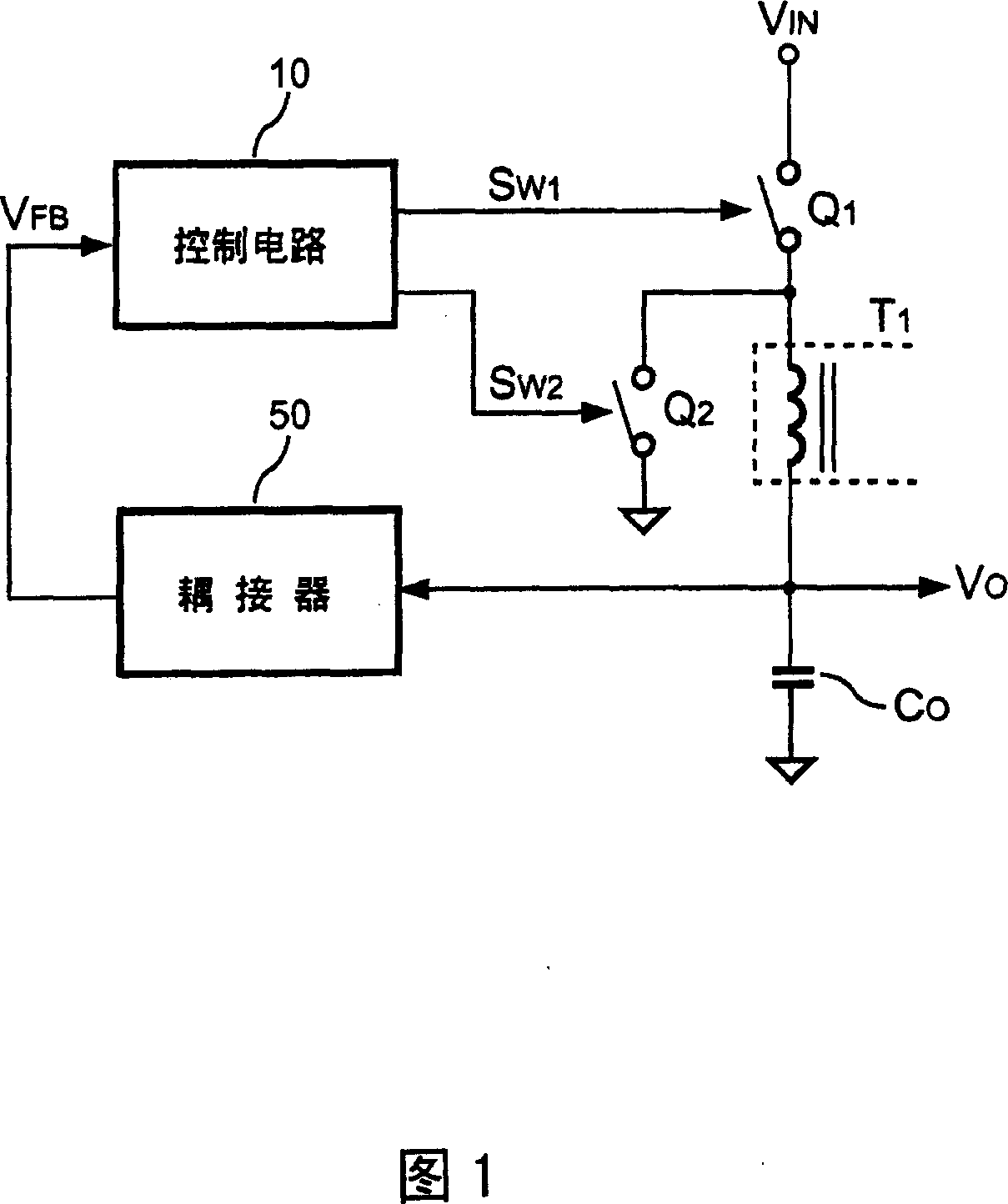
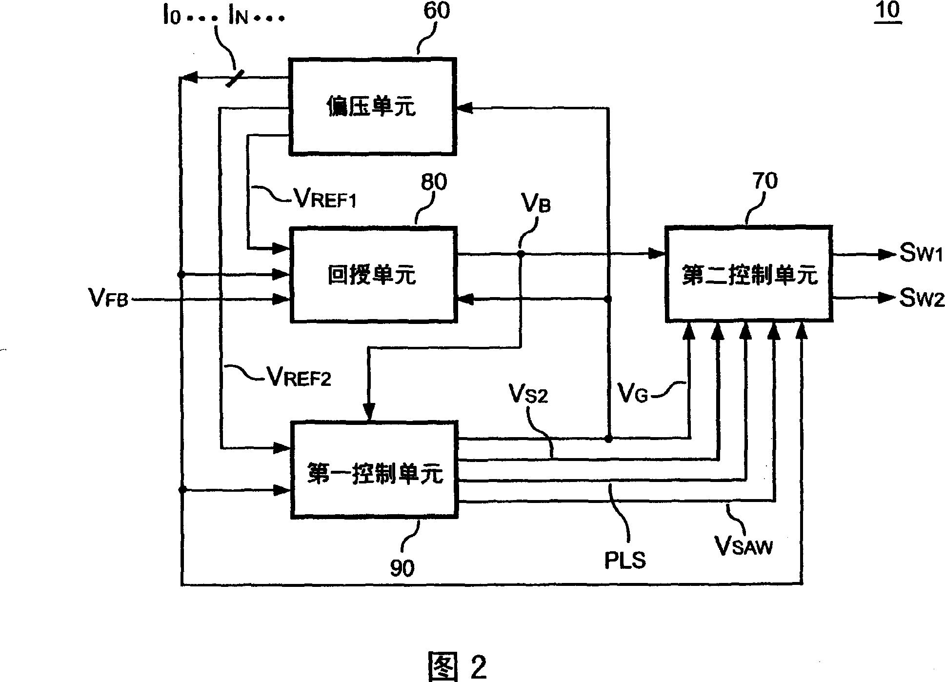
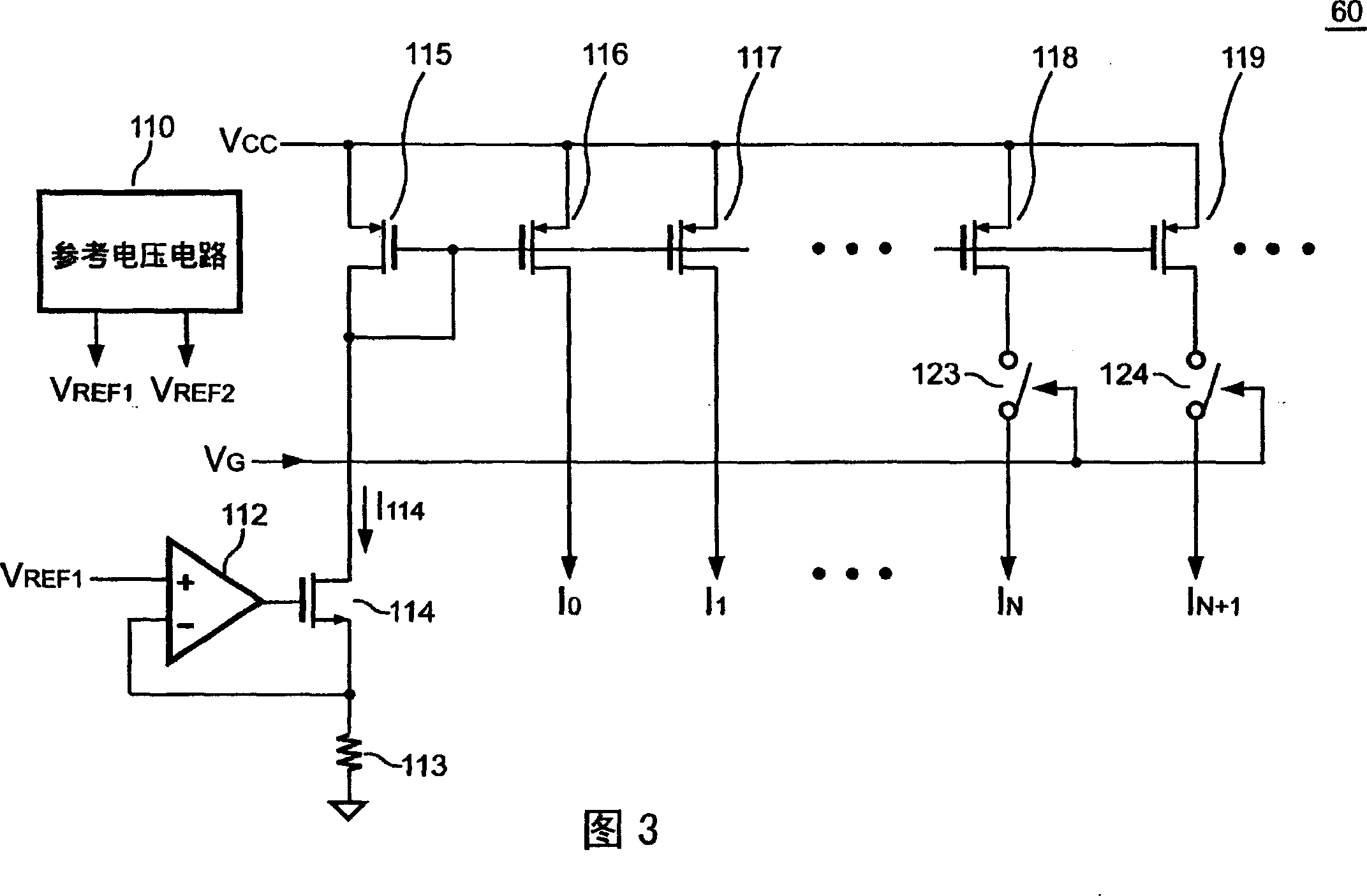
[0015] Referring to FIG. 2 , it is a schematic diagram of the control unit 10 of the switching regulator of the present invention. A bias unit 60 generates a first reference voltage V REF1 , a second reference voltage V REF2 with bias current I 0 ··I N ··. 1, a feedback unit 80 is coupled to an output terminal V of the switching regulator through a coupler 50 O , to receive an output signal V FB , and output a feedback signal V according to the output load condition B . A first control unit 90 receives the second reference voltage V REF2 with the feedback signal V B , used to output an oscillation signal PLS, a sawtooth signal V SAW , an energy-saving signal V G with an auxiliary control signal V S2 . A second control unit 70 is based on the feedback signal V B , the sawtooth signal V SAW , the auxiliary control signal V S2 , the energy-saving signal V G and the oscillating signal PLS to output a switching signal S W1 with an auxiliary switching signal S W2 ,...
PUM
 Abstract
Description
Claims
Application Information