
Extingushing system for fuel cell

A fire extinguishing system and fuel cell technology, applied in the field of fire extinguishing systems, can solve the problems of fuel cells without fire extinguishing systems and fire control limitations

Inactive Publication Date: 2007-02-28
LG ELECTRONICS INC +1
View PDF0 Cites 4 Cited by
  • Summary
  • Abstract
  • Description
  • Claims
  • Application Information

AI Technical Summary

Problems solved by technology

[0010] However, there is no special fire extinguishing system in the above-mentioned prior art fuel cells, although the fuel cells are in danger of catching fire due to system overheating or the like due to the characteristics of the system generating electricity and heat.
Thus, prior art fuel cells have limitations in controlling fires in the early stages of a fire

Method used


Image

  • Extingushing system for fuel cell
  • Extingushing system for fuel cell
  • Extingushing system for fuel cell

Examples


Embodiment Construction

[0018] Hereinafter, a fire extinguishing system for a fuel cell according to the present invention will be described with reference to an embodiment shown in the drawings.

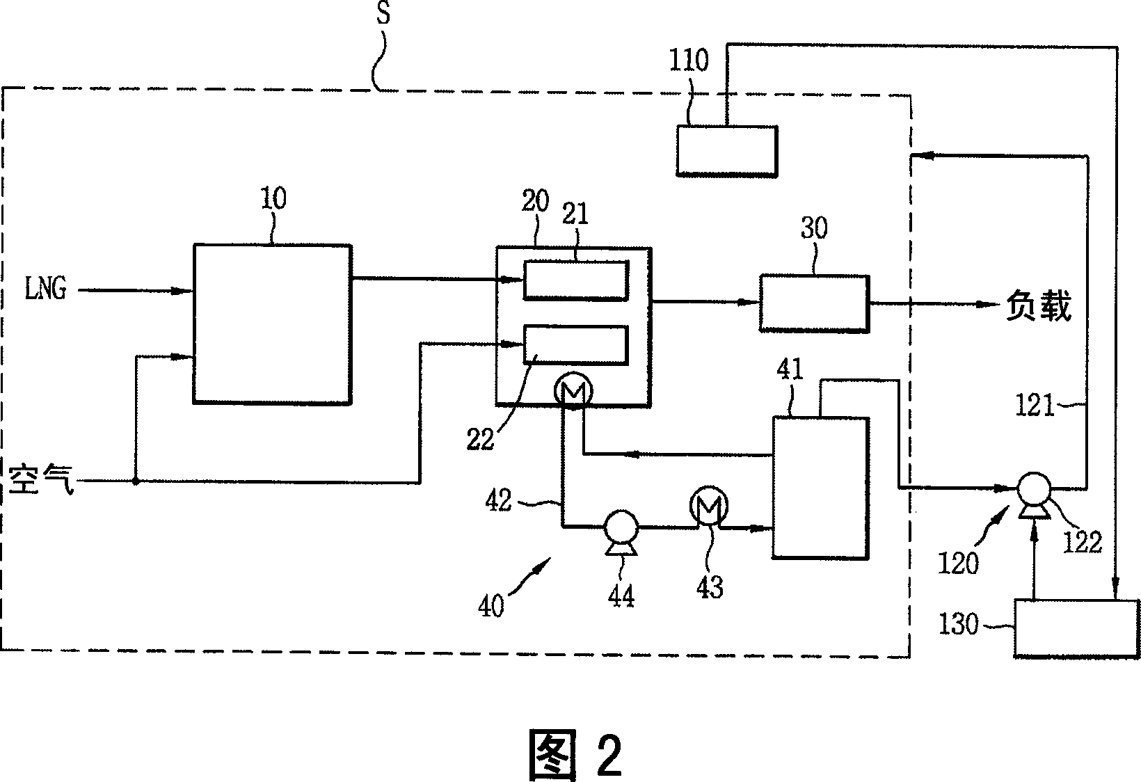
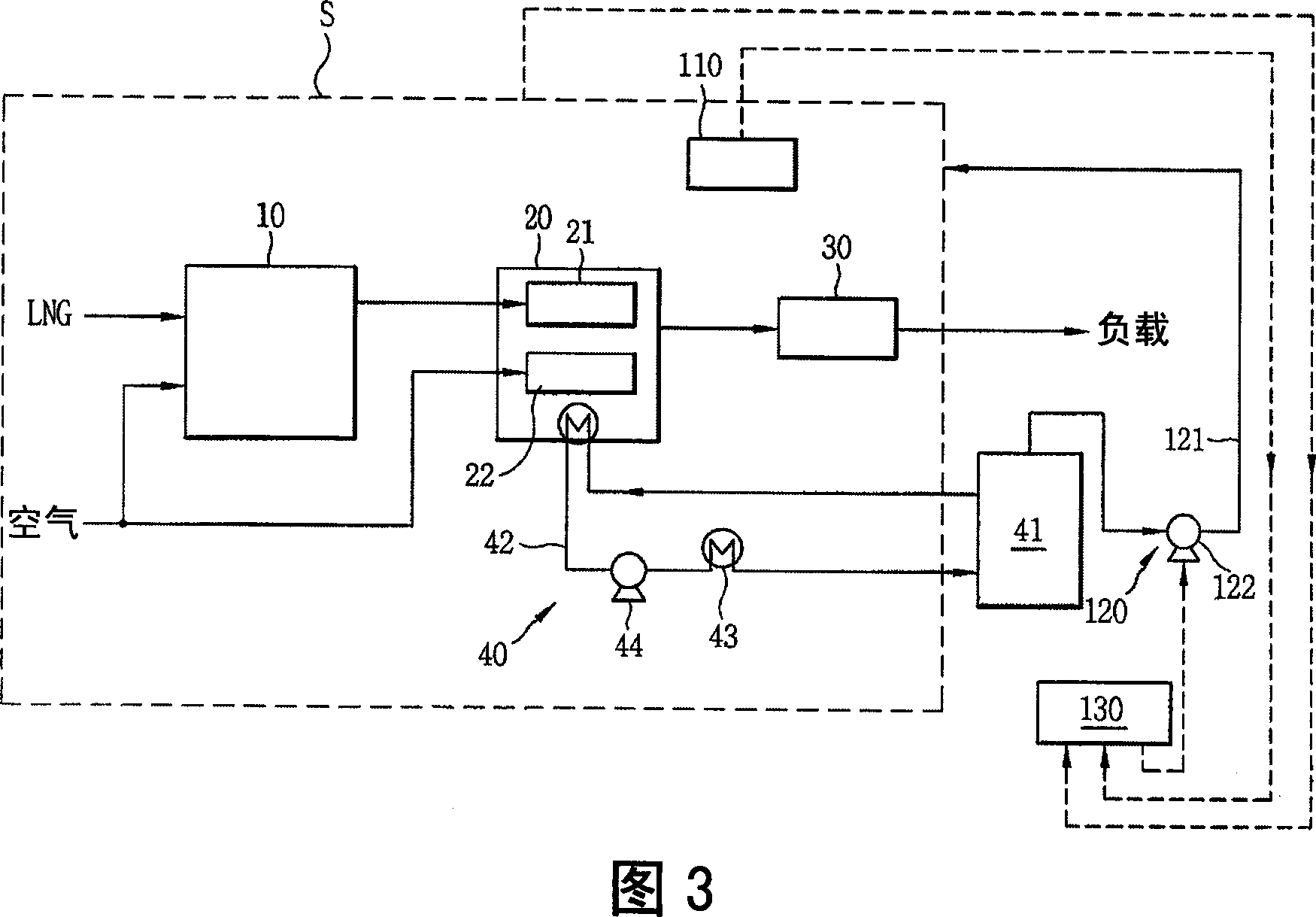
[0019] FIG. 2 is a system diagram of one example of a fuel cell with a fire extinguishing system according to the present invention. 3 is a system diagram of a modified example of a fuel cell with a fire extinguishing system according to the present invention.

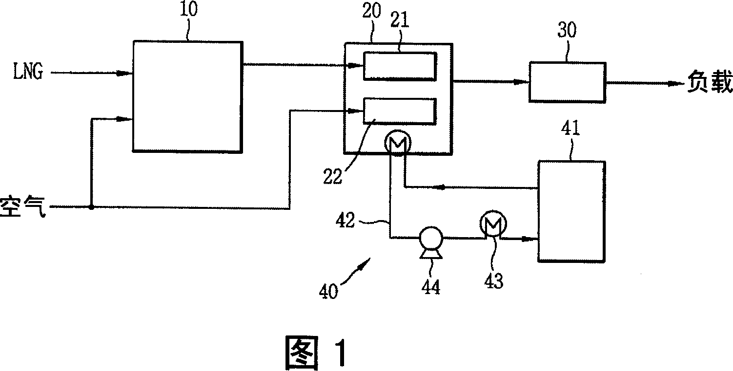
[0020] As shown in the figure, the fuel cell according to the present invention includes a reformer unit 10 for purifying hydrogen from LNG; a stack unit 20 provided with a fuel electrode 21 receiving purified hydrogen and an air electrode 22 receiving oxygen from air , for generating electricity and heat through the electrochemical reaction between hydrogen and oxygen; the power conversion unit 30, connected with the output end of the stack unit 20, for supplying electricity to the load; the heat exchange unit 40, for supplying the The reformer u...


PUM


Abstract

An extinguishing system for a fuel cell system comprises: a temperature sensing unit installed at the stack unit; an extinguishing unit operated according to a value sensed by the temperature sensing unit; and a control unit electrically connected to the temperature sensing unit and the extinguishing unit. Even if the system is overheated, or a fire takes place, this is sensed and the water filled in the water storage tank is automatically sprayed on the fuel cell stack, thereby preventing overheating of the fuel cell. Even in case of fire, the fire is rapidly extinguished at an early stage, thereby ensuring the stability of the system and preventing the risk of a fire in a building caused by the fuel cell.

Description

technical field [0001] The present invention relates to a fuel cell, and more particularly, to a fire extinguishing system for a fuel cell capable of preventing overheating or ignition of the fuel cell. Background technique [0002] In general, a fuel cell is a device that converts fuel energy directly into electricity. This fuel cell is a fuel cell system in which an anode and a cathode are provided on both sides of a polymer electrolytic membrane, and the system uses hydrogen as a fuel by an electrochemical oxidation reaction at the anode (oxidation electrode or fuel electrode). The movement of electrons generated when the oxygen used as the oxidant undergoes an electrochemical reduction reaction at the cathode (reduction electrode or air electrode) generates electrical energy, and the fuel cell system can also be regarded as a power plant. [0003] According to the operating temperature and main fuel type, the above fuel cells are divided into alkaline fuel cells (AFC), ...

Claims


Application Information

Patent Timeline
Patent Type & Authority Applications(China)
IPC IPC(8): H01M8/00
CPCH01M8/2475H01M8/04029H01M8/04738H01M8/04679H01M8/04373H01M8/04768H01M8/04365H01M8/04731H01M8/04223H01M8/04828Y02E60/50H01M8/241H01M8/2457H01M8/04
Inventor 金起东陆炯圭
Owner LG ELECTRONICS INC
Learn More