
Switch plug for wire terminal

A technology of wire terminals and plugs, which is applied to the parts of the connection device, the manufacture of contacts, and electrical components, etc., and can solve the problems that the second plug 22 is easy to fall off, high-frequency vibration, and urgent

Active Publication Date: 2007-02-28
SUNONWEALTH ELECTRIC MACHINE IND
View PDF0 Cites 0 Cited by
  • Summary
  • Abstract
  • Description
  • Claims
  • Application Information

AI Technical Summary

Problems solved by technology

[0007] 1. The second plug 22 is easy to fall off: the position between the first plug 21 and the second plug 22 is only set by the card pin and the socket, and only a slight friction is used to achieve the fastening purpose, and the heat dissipation system equipment is in operation. Can produce high-frequency vibration again, therefore be easy to cause the second plug 22 to fall off
[0008] 2. The second plug 22 is not easy to disassemble: In view of the aforementioned problem that the second plug 22 is easy to fall off, it can be solved by increasing the friction between the pin and the socket, or by other embedded designs such as bumps and slots When, it is easy to cause the difficulty of disassembly or assembly between the first and second plugs
[0009] Therefore, in order to completely solve the two serious shortcomings of the second plug, which is easy to fall off and difficult to disassemble, so as to meet the national safety standards, it is urgent to improve the combination structure of the wire terminal

Method used


Image

  • Switch plug for wire terminal
  • Switch plug for wire terminal
  • Switch plug for wire terminal

Examples


Embodiment Construction

[0027] In order to describe in detail the relative positions and functions of the various components of the present invention, the following preferred embodiments are listed and described below with accompanying drawings.

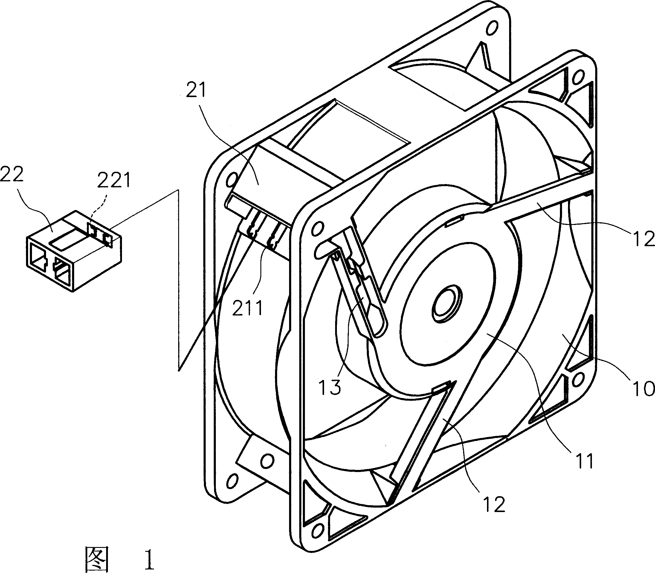
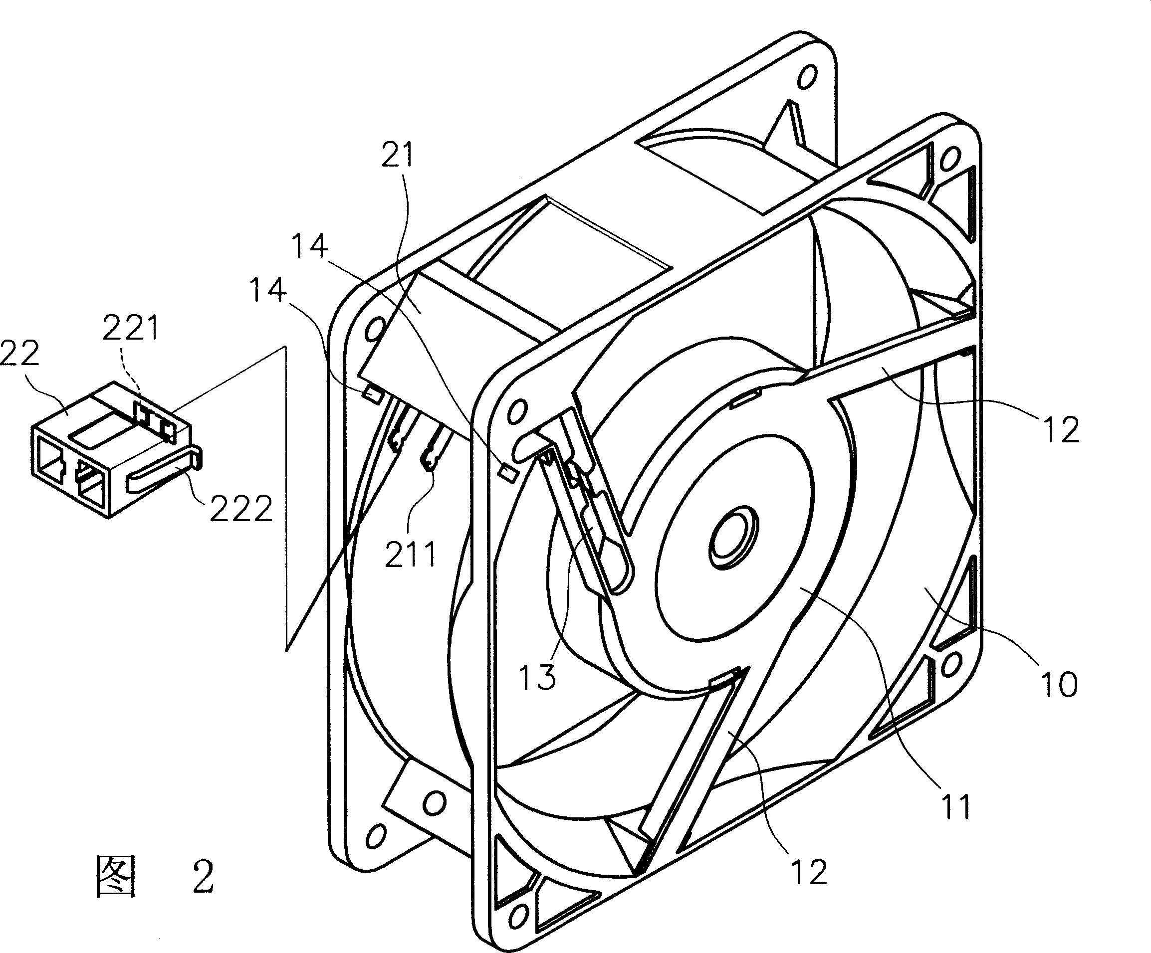
[0028] A wire terminal plug provided by the present invention is used on the frame body 10 of various heat dissipation system equipment. As shown in FIG. A motor stator and a motor rotor can be installed and positioned. The motor base 11 and the frame body 10 are connected by a plurality of ribs 12, and one of the ribs 12 is provided with a wire groove 13, and the wires connected to the motor stator are along the wire groove. 13 protrudes, and a terminal is provided at the position where the wire groove 13 is connected to the frame body 10 .

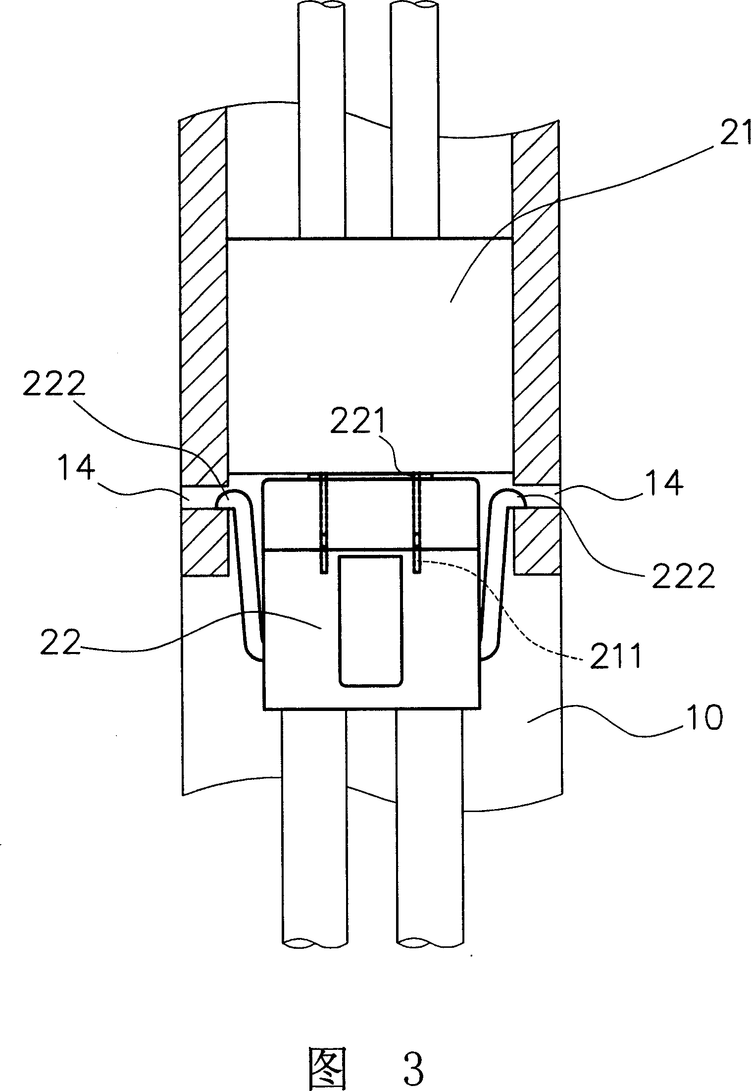
[0029] As shown in Figure 2 and Figure 3, the terminal includes a first plug 21 and a second plug 22, the first plug 21 is connected and fixed with the wire connected to the motor stator, and one end has a pin 211, an...


PUM


Abstract

The invention relates to a plug of wire terminal, which arranges first and second plugs at the frame of heat radiator. Wherein, the first plug is connected to the wire of motor stator of heat radiator and fixed on then frame; the second plug is connected to the connecting wire with clamping pins around; the part of heat radiator relative to the clamping pins has clamping returning holes fixing the clamping pins. The invention can confirm the fixing position of second plug, even at high-frequency vibration, and via the quick detachment of clamping returning holes; the second plug can quickly detach, to convert variable wires.

Description

technical field [0001] The invention relates to a wire terminal plug, which is a transfer terminal used in various heat dissipation system equipment, and through the terminal structure design of a standard plug, the requirement for converting various wires is met. Background technique [0002] The wire diameter of the heat dissipation system equipment varies according to its conductivity resistance. For example, the wire diameter of the wire specification is UL 1015 18AWG is 2.80mm, while the wire diameter of the wire specification is UL 1015 22AWG is 2.40mm. [0003] However, it is not economical to produce a variety of corresponding specifications for the frame of the heat dissipation system equipment according to the wire diameter. Therefore, in order to meet the market demand for various wires, it is necessary to use a standard plug terminal to achieve conversion. Various wire needs. [0004] As shown in Figure 1, the conventional wire terminal is arranged on the frame ...

Claims


Application Information

Patent Timeline
Patent Type & Authority Applications(China)
IPC IPC(8): H01R43/16H01R13/629
Inventor 洪银树蔡佳景
Owner SUNONWEALTH ELECTRIC MACHINE IND
Learn More