

Current detecting circuit, load drive, and storage
A current detection circuit and current detection technology, applied in measurement devices, measurement of current/voltage, measurement of electrical variables, etc., can solve problems such as power efficiency reduction, current detection resistance loss, inability to detect load current, etc., to reduce power consumption. Effect
- Summary
- Abstract
- Description
- Claims
- Application Information
AI Technical Summary
Problems solved by technology
Method used
Image


Examples
Embodiment Construction
[0055] Embodiments of a current detection circuit, a load drive circuit using the current detection circuit, and a storage device having a motor driven by the load drive circuit according to the present invention will be described below with reference to the drawings.
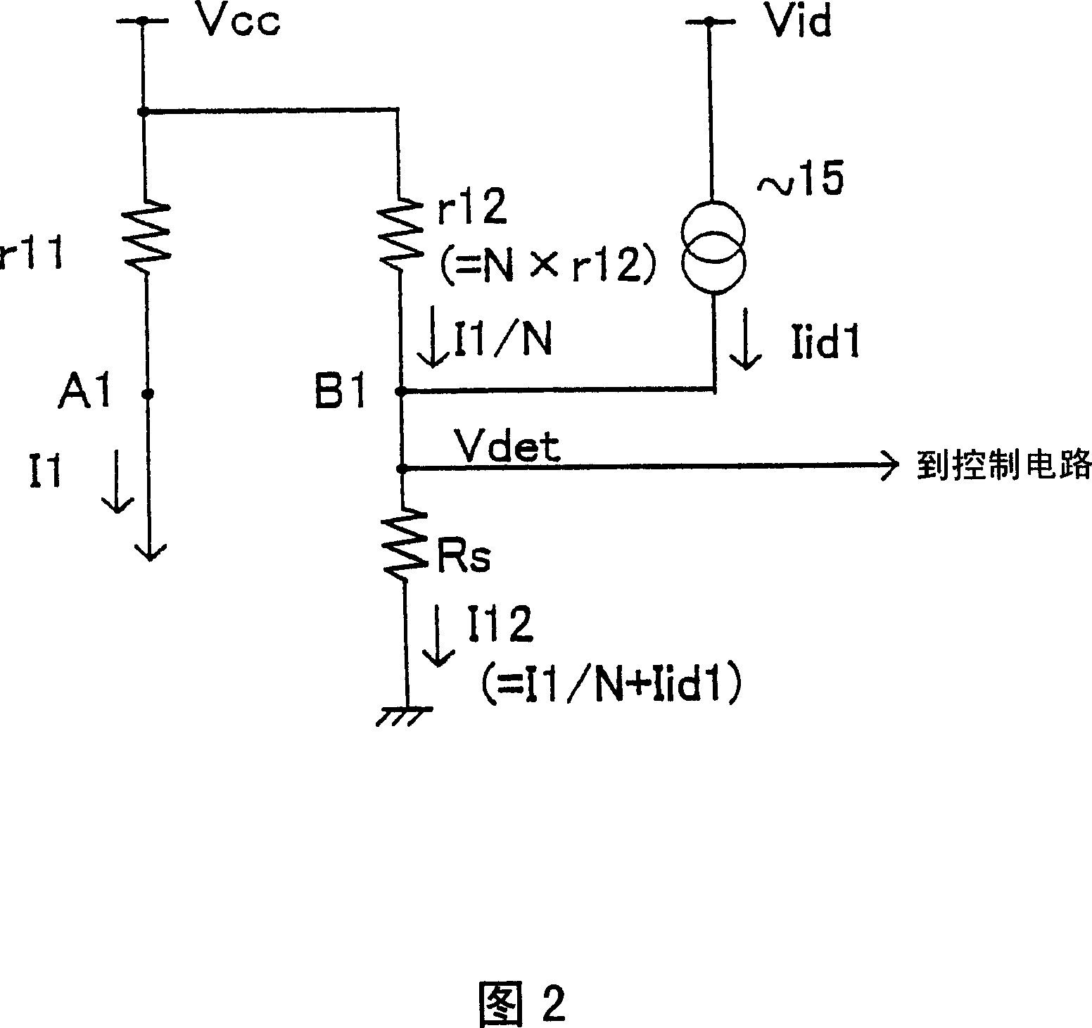
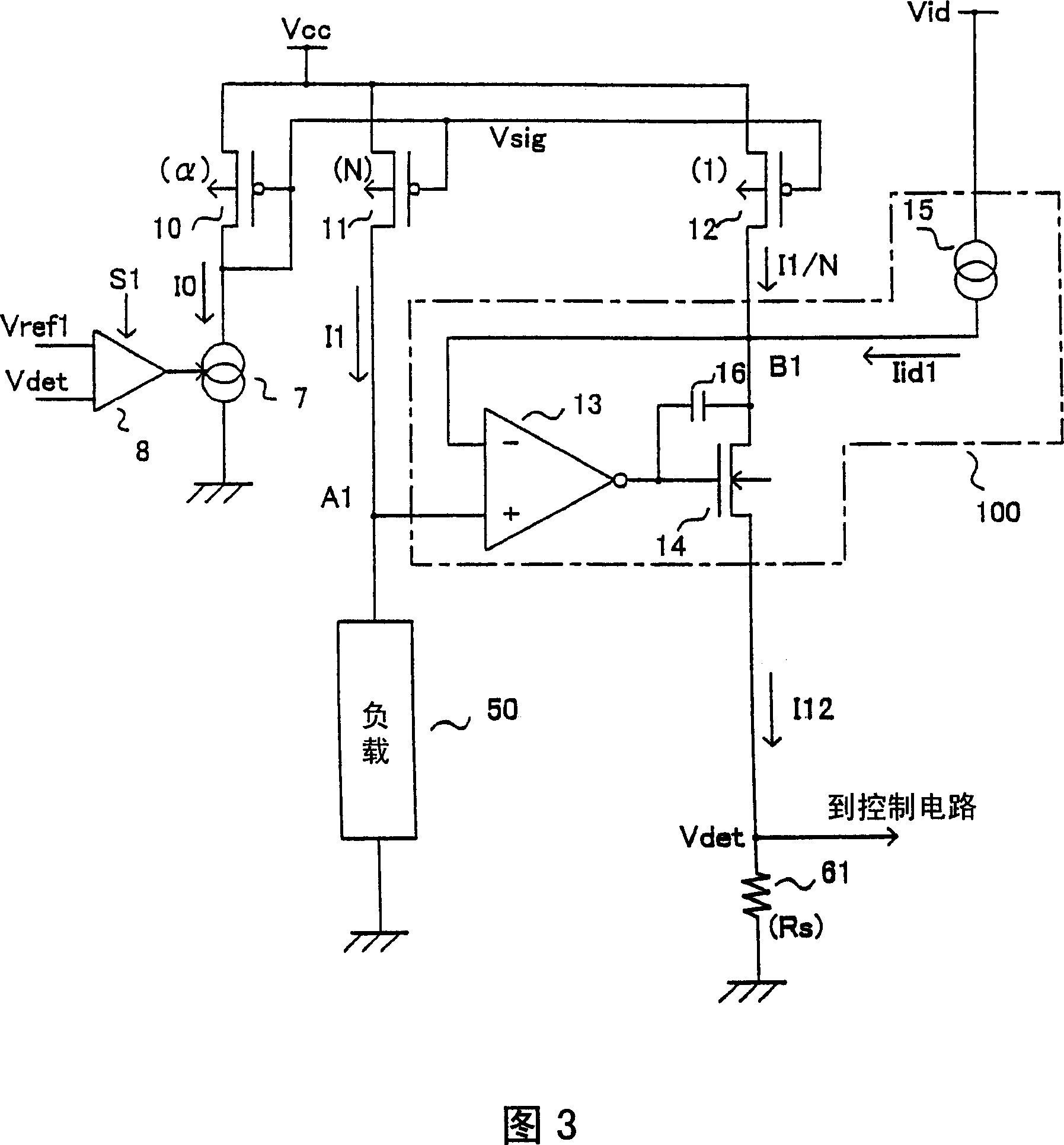
[0056] Fig. 1 shows a current detection circuit of the first embodiment. Since the load is driven by this current detection circuit, the current detection circuit in FIG. 1 may also be called a load drive circuit or a load drive device.
[0057] In FIG. 1, a P-type MOS transistor 11 as a first transistor is connected in series with a load 50 and connected to a first power supply voltage V CC and between. The first transistor 11 is turned on when a switching signal S1 (L level) as a control signal is applied to the gate, and a load current (output current) I1 flows. In addition, unless otherwise specified in this specification, a voltage means a potential with respect to a ground voltage.
[0058] Since the s...
PUM
 Abstract
Description
Claims
Application Information