Resistance heating type melt-drawn machine for manufacturing optical fiber devices

A technology of resistance heating and optical fiber devices, applied in the coupling of optical waveguides, etc., to achieve safe use, adjustable heating temperature, and good stability

Inactive Publication Date: 2007-03-07
CENT SOUTH UNIV
View PDF0 Cites 12 Cited by
  • Summary
  • Abstract
  • Description
  • Claims
  • Application Information

AI Technical Summary

Problems solved by technology

[0009] The technical problem to be solved by the present invention is to overcome the problems existing in the flame heating melting tapering machine, and provide a kind of electric resistance

Method used


Image

  • Resistance heating type melt-drawn machine for manufacturing optical fiber devices
  • Resistance heating type melt-drawn machine for manufacturing optical fiber devices
  • Resistance heating type melt-drawn machine for manufacturing optical fiber devices

Examples


Embodiment Construction

[0033] The specific embodiments of the present invention will be described below with reference to the accompanying drawings.

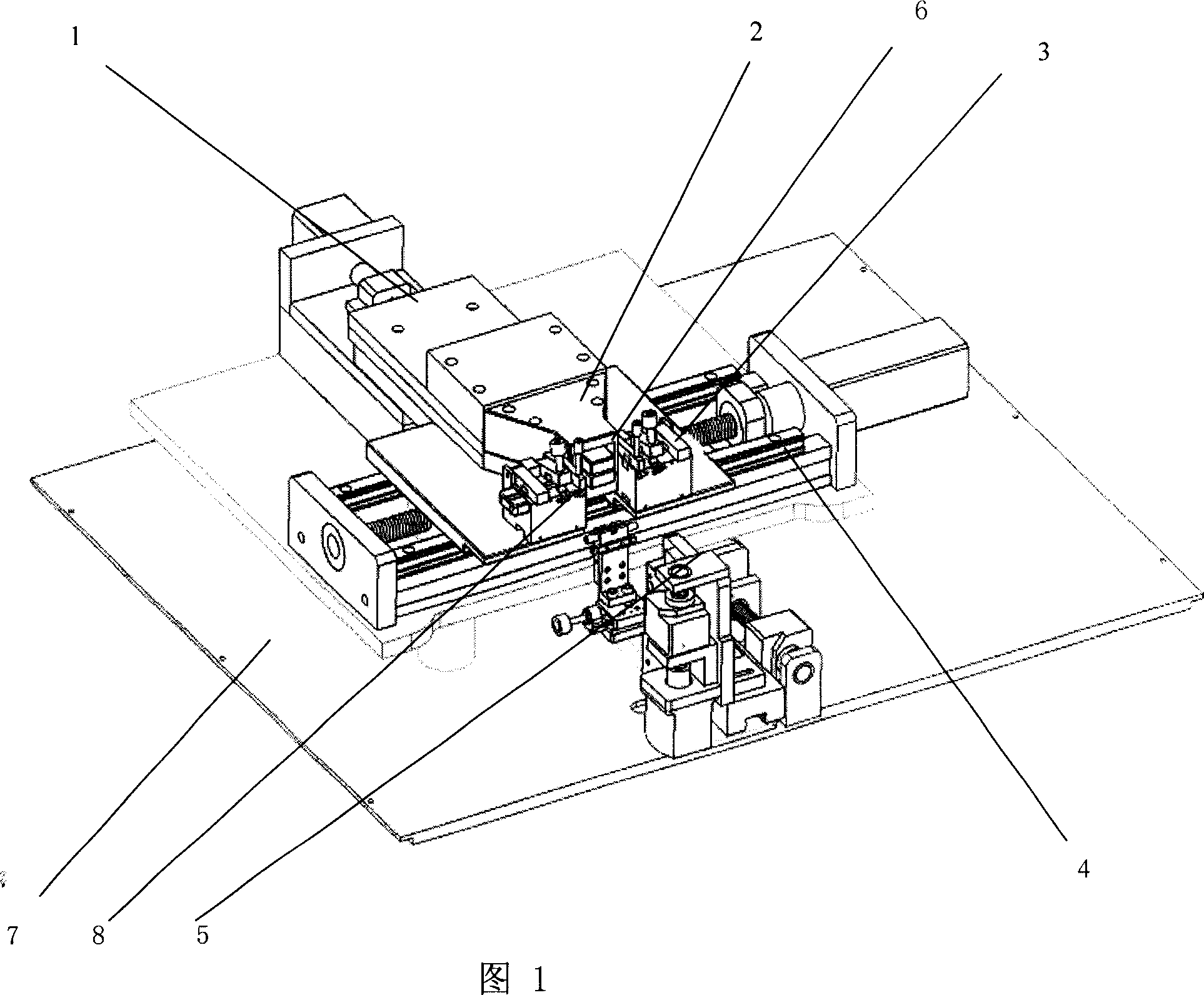
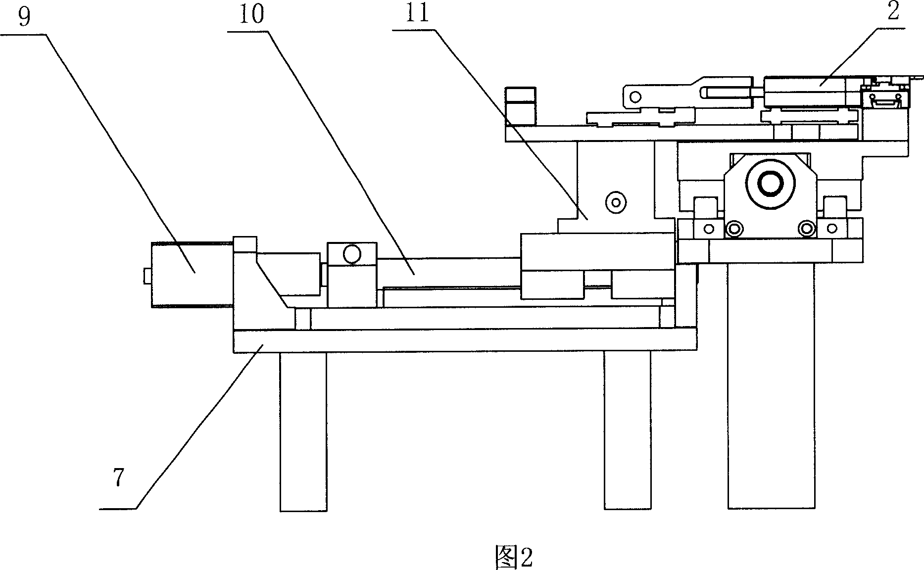
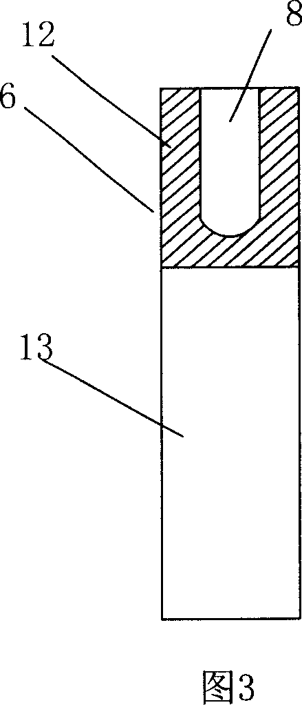
[0034] Referring to Figure 1, Figure 2, Figure 3 and Figure 4, an optical fiber drawing mechanism 4 is provided on the frame 7, an optical fiber clamp 3 is provided on the optical fiber drawing mechanism 4, and an optical fiber packaging mechanism 5 is provided on the frame 7 The heater movement mechanism 1 is provided on the frame 7, the resistance heater 2 is provided on the heater movement mechanism 1, the heater 2 is provided with a resistance heating element 6, and the front end of the resistance heating element 6 is provided with an optical fiber clamp 3 Corresponding to the heating tank 8, the resistance heating element 6 is electrically connected with a temperature control device.

[0035] The heater movement mechanism 1 is composed of a manual lifting adjustment device 11 and an automatic feeding device 10, which is arranged on the frame 7, the h...


PUM


Abstract

This invention discloses one resistance heating fusion tamper machine to process light fiber parts, which comprises resistance heater and its movable structure, fiber stretching structure, shell rack, fiber clamper and fiber package structure, wherein, the rack is set with heater movable structure with heater set; the heater is set with resistance heating part with front set with fiber clamper heating tank; the resistance heater is connected with temperature control device.

Description

Technical field [0001] The invention relates to an equipment for manufacturing optical fiber communication devices and optical fiber sensor devices, in particular to a fusion taper machine for manufacturing optical fiber devices by placing optical fiber devices in a high-temperature environment for melting and rheology. The high-temperature environment adopts resistance heating Way to get. Background technique [0002] The fusion tapering manufacturing process is a general method for making optical fiber devices such as optical fiber couplers. The basic process is: two (or more) single-mode (or multi-mode) fibers with the coating layer removed are brought together in a certain way. It is heated and melted at high temperature and stretched to both sides at the same time to form a bidirectional conical structure to realize optical fiber device manufacturing. The equipment used to manufacture the fusion taper of the optical fiber device is a fusion taper machine. The current fusion ...

Claims


Application Information

Patent Timeline
IPC IPC(8): G02B6/24G02B6/255
Inventor 段吉安帅词俊廖平
Owner CENT SOUTH UNIV
Why Eureka
Try Eureka