Control circuit of DC-DC converter and its control method

A control circuit, DC-DC technology, applied in the direction of analog conversion, code conversion, control/regulation system, etc.

Inactive Publication Date: 2007-03-07
SOCIONEXT INC
View PDF3 Cites 7 Cited by
  • Summary
  • Abstract
  • Description
  • Claims
  • Application Information

AI Technical Summary

Problems solved by technology

That is, the gain must be controlled statically

Method used


Image

  • Control circuit of DC-DC converter and its control method
  • Control circuit of DC-DC converter and its control method
  • Control circuit of DC-DC converter and its control method

Examples


Embodiment Construction

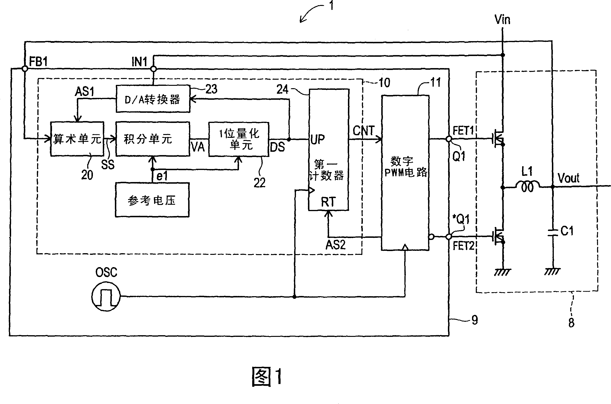
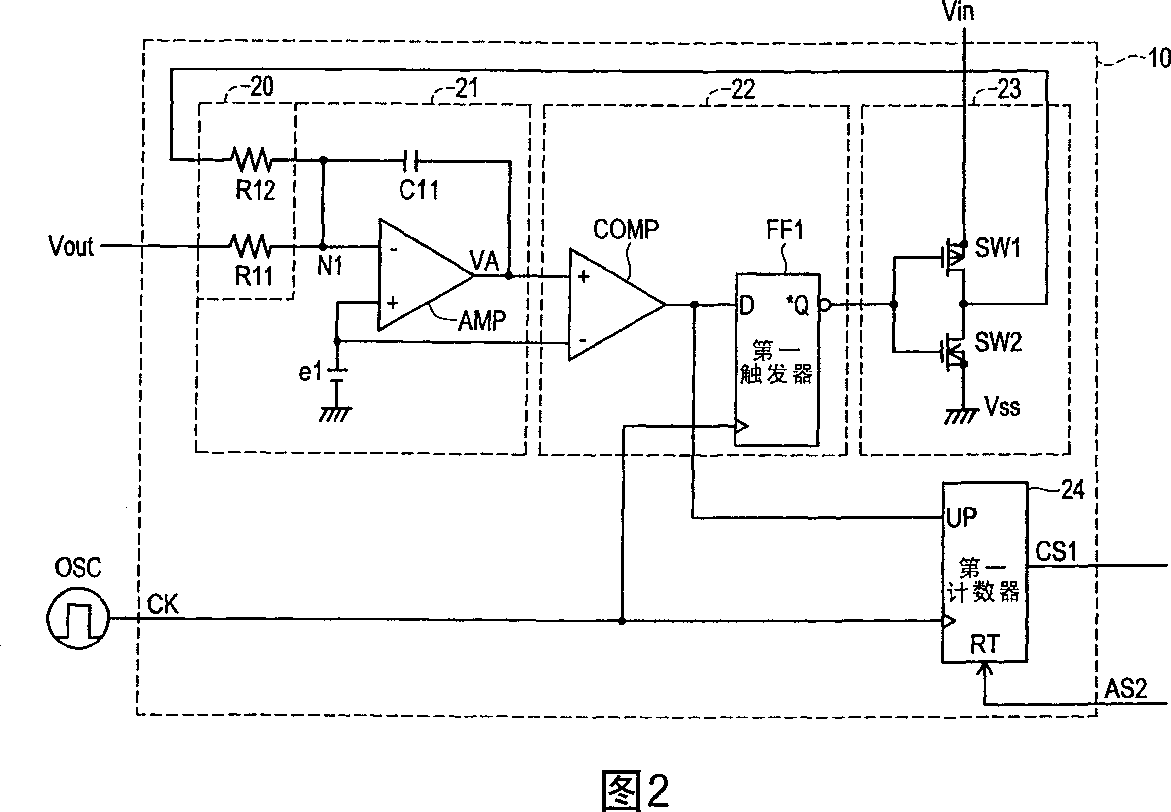
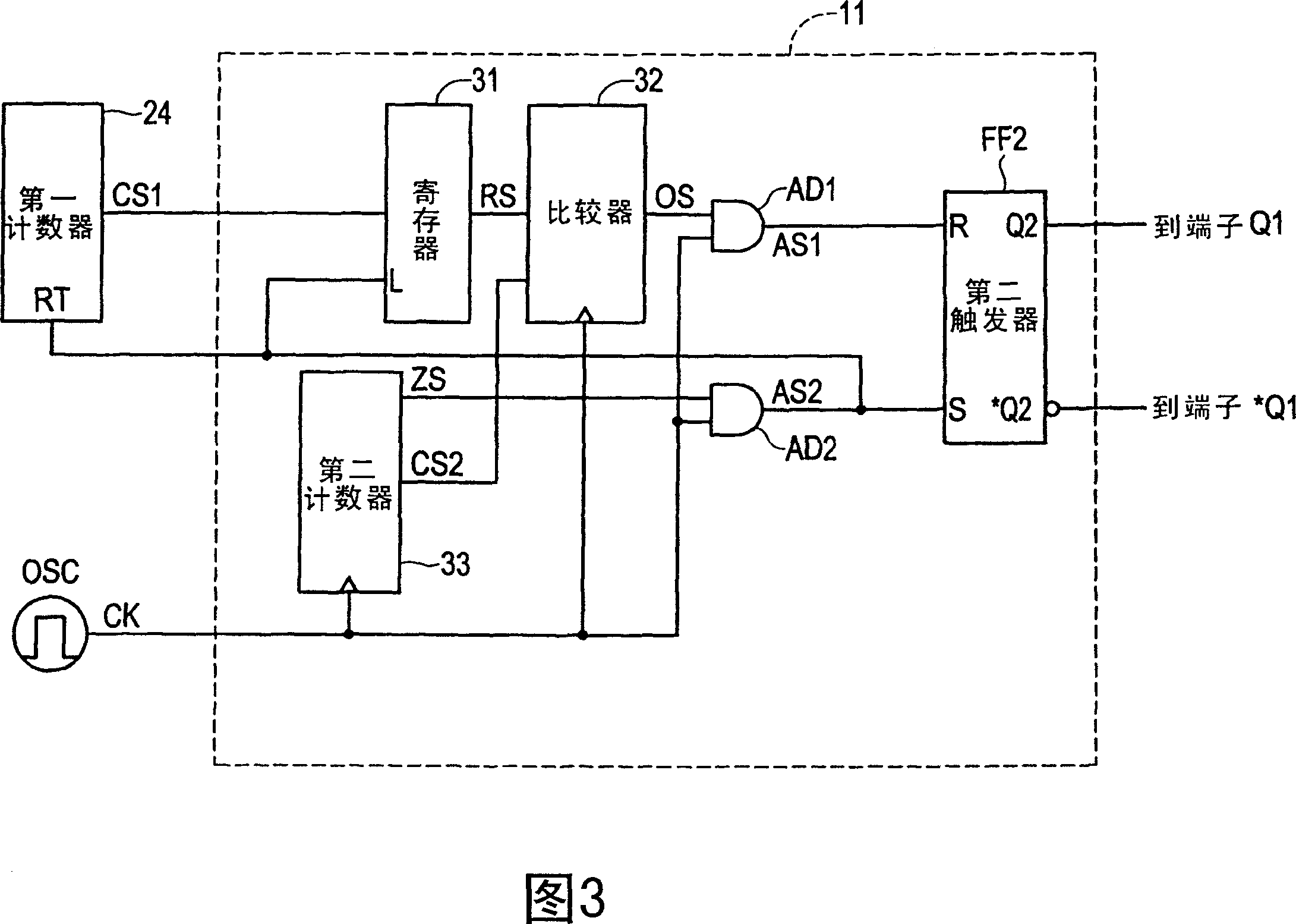
[0025] Referring to FIG. 1 to FIG. 6, the specific embodiment of the control circuit of the DC-DC converter with the digital error amplifier of the present invention will be described in detail. First, in FIG. 6 , a synchronous rectification switching type DC-DC converter 100 with an analog error amplifier is illustrated. The output voltage Vout of the DC-DC converter is input to a terminal FB1 of the control unit 109 . Between the terminal FB1 and the ground voltage Vss, a resistor R1 and a resistor R2 are connected in series to divide the output voltage Vout. The reference voltage e1 is input to the non-inverting input of the error amplifier ERA1, and the divided voltage of the output voltage Vout is input to the inverting input. Between the inverting input terminal and the output terminal of the error amplifier ERA1, a resistor R3 and a capacitor C2 are connected as a feedback circuit. The series impedance of resistor R3 and capacitor C2 is the feedback resistor Z. The o...


PUM


Abstract

To present a control circuit of a DC-DC converter to be incorporated in a logic circuit, having a digital error amplifier capable of controlling the gain depending on an input voltage and an output voltage, without requiring a resistance or a capacitor of high precision used in a feedback circuit or the like. A SigmaDelta AD converter type error amplifier 10 includes an arithmetic unit 20 , an integrating unit 21 , a 1-bit quantizing unit 22 , a D / A converter 23 , and a first counter 24 . The arithmetic unit 20 outputs a differential signal of an output voltage Vout and an average output voltage AV. The integrating unit 21 outputs an integral signal by integrating the differential signal. The 1-bit quantizing unit 22 outputs a 1-bit digital signal by quantizing the integral signal. The D / A converter 23 converts from digital to analog depending on a 1-bit digital signal. A digital PWM circuit 11 determines the on-duty of the main switching element of the DC-DC converter depending on the pulse density of the D / A converter 23.

Description

technical field [0001] The present invention relates to the control of a DC-DC converter, in particular, to a control circuit of a DC-DC converter which can be easily constituted in a logic circuit and a control method thereof. Background technique [0002] In a control circuit of a synchronous rectification switching type DC-DC converter with an analog error amplifier, the analog error amplifier has a resistor or capacitor as a feedback circuit. In the case of fluctuations in the input voltage of the DC-DC converter or variable control of the output voltage of the DC-DC converter, it is required that the error amplifier does not oscillate. In order to set the gain so that the phase of the feedback circuit has a margin, when designing a DC-DC converter, the design of the phase compensation of the feedback circuit must take into account the relationship between the input and output voltages. That is, the gain must be controlled statically. [0003] Other related art is disc...

Claims


Application Information

Patent Timeline
Patent Type & Authority Applications(China)
IPC IPC(8): H02M3/155
CPCH03M3/43H03M3/456H02M2001/0022H03M3/506H02M3/157H02M1/0022H02M3/155
Inventor 吉野孝博
Owner SOCIONEXT INC
Why Eureka
Try Eureka