Method for manufacturing elliptically polarizing plate and image display device using the elliptically polarizing plate

A technology of ellipsoidal polarization and polarizer, applied in the direction of identification devices, optics, optical components, etc., can solve the problems that have not yet found a widely applicable method, difficult to adjust, etc., and achieve the optimization of ellipsoidal polarizer, excellent adhesion, and low cost Effect

Inactive Publication Date: 2007-03-07
NITTO DENKO CORP
View PDF16 Cites 18 Cited by
  • Summary
  • Abstract
  • Description
  • Claims
  • Application Information

AI Technical Summary

Problems solved by technology

However, the problem with this approach is that it is difficult to adjust
[0007] At the same time, at present, the angle between the absorption axis of the polarizing film and the slow axis of each phase difference plate is adjusted according to the product, and a widely applicable way to optimize this angle has not been found yet.

Method used


Image

  • Method for manufacturing elliptically polarizing plate and image display device using the elliptically polarizing plate
  • Method for manufacturing elliptically polarizing plate and image display device using the elliptically polarizing plate
  • Method for manufacturing elliptically polarizing plate and image display device using the elliptically polarizing plate

Examples


Embodiment 1

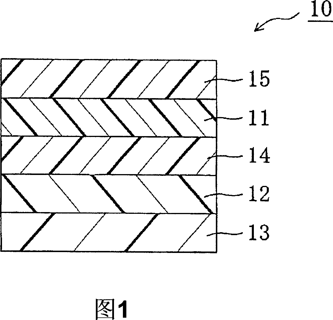
[0169] I. prepare the elliptical polarizer as shown in Figure 1

[0170] I-a. Alignment treatment of substrate (preparation of alignment substrate)

[0171] Alignment treatment is performed on the substrate to prepare an alignment substrate.

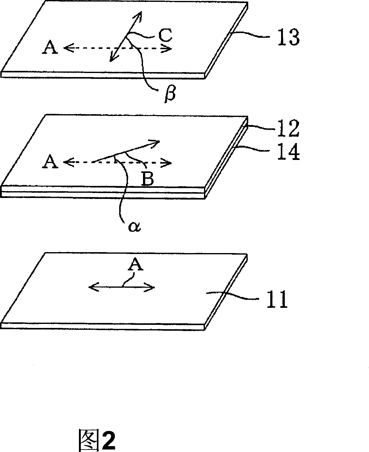
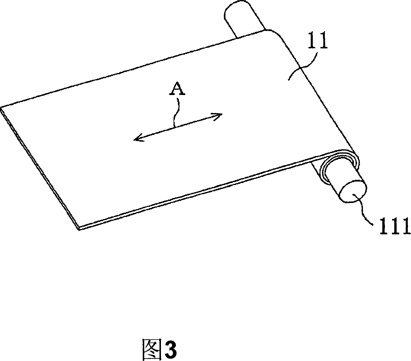
[0172] Substrates (1) to (6): Each alignment substrate was formed by rubbing the surface of a polyethylene terephthalate (PET) film (50 μm in thickness) with a rubbing cloth at the rubbing angle shown in Table 1 below.

[0173] Substrate

Friction angle (angle α)

(1)

13°

(2)

-13°

(3)

23°

(4)

-23°

(5)

33°

(6)

-33°

[0174] I-b. Preparation of the first birefringent layer (the first birefringent layer formed on the substrate)

[0175] 10 g of a polymerizable liquid crystal exhibiting a nematic liquid crystal phase (Paliocolor LC242, trade name; purchased from BASF Group Corporation) and 3 g of a photopolymerization initiator for a...

Embodiment 2

[0192] The elliptically polarizing plate A01 was overlaid to measure the contrast. Table 1 shows that elliptically polarizing plates have a relationship represented by the expression β=2α+44°. For this elliptical polarizer, when the contrast ratio is 10, the minimum angle in all directions is 40°, the maximum angle is 50°, and the difference between the maximum and minimum angles is 10°. In actual use, when the contrast ratio in all directions is 10, the minimum angle of 40° is the preferred level. Moreover, the difference between the maximum and minimum angles is only 10°, so the elliptical polarizer has balanced visual characteristics, which is also a very preferable level in practical use.

Embodiment 3

[0194] The elliptically polarizing plate A21 was overlaid to measure the contrast. Table 1 shows that elliptically polarizing plates have a relationship represented by the expression β=2α+44°. For this elliptical polarizer, when the contrast ratio is 10, the minimum angle in all directions is 40°, the maximum angle is 60°, and the difference between the maximum and minimum angles is 20°. In actual use, when the contrast ratio in all directions is 10, the minimum angle of 40° is the preferred level.


PUM

PropertyMeasurementUnit
thicknessaaaaaaaaaa
thicknessaaaaaaaaaa
thicknessaaaaaaaaaa

Abstract

A process for producing an elliptical polarization plate of broadband and wide viewing angle having excellent properties with respect to an oblique direction; such an elliptical polarization plate; and an image display apparatus. There is provided a process for producing an elliptical polarization plate, comprising the steps of forming a first birefringent layer on a surface of transparent protective film, superimposing a polarizer on another surface of transparent protective film and forming a second birefringent layer on the surface of the first birefringent layer, wherein the first birefringent layer and the polarizer are respectively arranged on opposite sides of the transparent protective film, and wherein the first birefringent layer forming step comprises the steps of coating an alignment base material with a liquid crystal material, forming the first birefringent layer from the liquid crystal material on the base material and transferring the first birefringent layer onto the surface of transparent protective film, and wherein the angle between absorption axis of the polarizer and retardation axis of the first birefringent layer, a, and the angle between absorption axis of the polarizer and retardation axis of the second birefringent layer, ss, exhibit a given relationship.

Description

technical field [0001] The present invention relates to an elliptically polarized plate and an image display device using the elliptically polarized plate. More specifically, the present invention relates to a method of manufacturing an elliptically polarizing plate having excellent oblique characteristics and having a wide frequency band and a wide viewing angle at very high production efficiency, an elliptically polarizing plate obtained by the method, and an elliptically polarizing plate using the elliptically polarizing plate Plate image display device. Background technique [0002] Various optical films each having a combined polarizing film and retardation plate are generally used in various image display devices such as liquid crystal display devices and electroluminescent displays (EL) to obtain optical compensation. [0003] Generally, a circular polarizing plate which is one of the above-mentioned optical films can be manufactured by combining a polarizing film an...

Claims


Application Information

Patent Timeline
Patent Type & Authority Applications(China)
IPC IPC(8): G02B5/30G09F9/00G02F1/1335
CPCG02B5/3016G02F2001/133638G02F1/133638G02B5/30
Inventor 川本育郎梅本清司上条卓史米泽秀行秦和也
Owner NITTO DENKO CORP
Why Eureka
Try Eureka