
Trapper of sewing machine

A sewing machine and thread clamping technology, applied in the direction of sewing machine components, tension devices, sewing equipment, etc., can solve the problems of voltage drop, difficulty in correct control, increase in resistance heating, etc., to prevent voltage drop and suppress noise Affect and avoid the effect of fever

Inactive Publication Date: 2011-08-17
JUKI CORP
View PDF1 Cites 0 Cited by
  • Summary
  • Abstract
  • Description
  • Claims
  • Application Information

AI Technical Summary

Problems solved by technology

[0008] Therefore, there is a disadvantage that a resistance element with a large allowable power is required as the resistance element, and resistance heat generation is also increased.
[0009] On the other hand, if a resistance element with a small resistance value is used to limit heat generation, a voltage drop will occur in a low-tension region, such as when an AC servo motor is used for driving the upper shaft of a sewing machine, or a switching power supply is used for power supply. In a noisy environment, it is difficult to perform correct control

Method used


Image

  • Trapper of sewing machine
  • Trapper of sewing machine
  • Trapper of sewing machine

Examples


Embodiment Construction

[0038] (Overall structure of the embodiment)

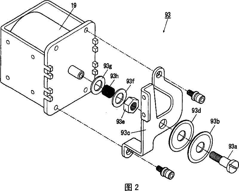
[0039] based on Figure 1 ~ Figure 4 The embodiments of the present invention will be described. The sewing machine 10 of the present embodiment is a sewing machine for performing needle movement and sewing in a direction perpendicular to the cloth feeding direction, that is, for performing so-called zigzag sewing. Although not shown, the above-mentioned sewing machine 10 includes a needle bar mechanism that performs up and down movement of the needle and movement of the needle, and a thread tension device that is arranged in the middle of the thread path of the sewing thread supplied to the needle and applies thread tension.

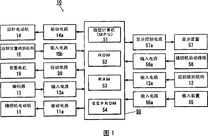
[0040] figure 1 It is a block diagram showing the overall configuration of the control circuit of the sewing machine 10. The control device 50 as a control mechanism of the needle bar mechanism performs operation control of each structure.

[0041] Hereinafter, each part will be described in detail.

[0042] (Se...


PUM


Abstract

The invention provides a thread tension device of a sewing machine controlling a wide range of thread tension while dispensing with a resistor with a large allowable current value. This thread tension device is provided with: a thread tension appliance (93) generating a tensile force to a sewing thread of a sewing machine; an actuator (19) becoming a drive source of the tensile force generation; a control means (50) outputting a control signal according to a target tensile force; and a driving circuit (20) driving the actuator by energizing a drive current according to the control signal. Thedrive circuit is provided with: detecting means (44, 45) connected to the actuator, detecting the drive current and capable of changing over a detection resistance value; and a resistor changeover means (35) changing over the detection resistance value by the target tensile force. When the target tensile force is larger than the prescribed value, the drive circuit detects the drive current at a small detection resistance value and controls the drive current.

Description

Technical field [0001] The present invention relates to a thread clamping device of a sewing machine having a driving source for adjusting the tension applied to the sewing thread. Background technique [0002] Conventionally, the following thread clamping devices are known, which have: a tension disc or a rotary tension type thread tensioner that applies tension to the sewing thread; and a voice coil motor (voice coil motor) that serves as a drive source for generating the tension. motor); and a control mechanism that controls the tension of the voice coil motor according to the increase or decrease in the amount of output current (for example, refer to Patent Document 1). [0003] The control mechanism of the thread clamping device shown in the above-mentioned document 1 has: a CPU that performs predetermined control according to a control program; a D / A converter that performs analog conversion on a control signal of the CPU; and a drive circuit that performs a The control sign...

Claims


Application Information

Patent Timeline
Patent Type & Authority Patents(China)
IPC IPC(8): D05B47/04
CPCD05B47/04
Inventor 伊藤文夫
Owner JUKI CORP
Learn More